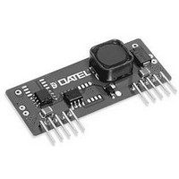
UNS-5/3-D12 Murata Power Solutions Inc, UNS-5/3-D12 Datasheet - Page 3

UNS-5/3-D12
Manufacturer Part Number
UNS-5/3-D12
Description
DC/DC Converter
Manufacturer
Murata Power Solutions Inc
Series
UNSr
Datasheet
1.UNS-53-D12.pdf
(5 pages)
Specifications of UNS-5/3-D12
Dc / Dc Converter O/p Type
Fixed
No. Of Outputs
1
Input Voltage
6V To 16.5V
Power Rating
15W
Output Voltage
5V
Output Current
3A
Supply Voltage
12V
Dc / Dc Converter Case Style
SIP
Output Power
15 W
Input Voltage Range
6 V to 16.5 V
Input Voltage (nominal)
12 V
Number Of Outputs
1
Output Voltage (channel 1)
5 V
Output Current (channel 1)
3 A
Package / Case Size
SIP
Lead Free Status / RoHS Status
Contains lead / RoHS non-compliant
Typical @ T
Output
Absolute Maximum Ratings
Input Voltage Range:
Input Current
Input Filter Type
Overvoltage Protection
Reverse-Polarity Protection
On/Off Control (Pin 5)
V
Temperature Coefficient
Ripple/Noise (20MHz bandwidth)
Line/Load Regulation
Efficiency
Current Limiting
Transient Response (50% load step)
Switching Frequency
Operating Temperature:
Storage Temperature
Dimensions: SIP Models
mance. Listed specifications assume C
UNS Series devices require external input/output capacitors to achieve rated perfor
Input Voltage:
Input Reverse-Polarity Protection
Output Overvoltage Protection
Output Current
Storage Temperature
Lead Temperature (soldering, 10 sec.)
See Technical Notes.
Output Ripple/Noise can be reduced with external capacitors. See Technical Notes.
UNS Series converters have no minimum-load requirements.
Current limiting initiates at approximately 5% above rated load.
DIP models have a standoff which makes their total above-board height 0.44 inches.
These are stress ratings. Exposure of devices to any of these conditions may adversely
affect long-term reliability. Proper operation under conditions other than those listed in the
Performance/Functional Specifications Table is not implied.
OUT
Input
Dynamic Characteristics
Environmental
Physical
"D5" and "D5D" Models
"D12" and "D12D" Models
Without Derating
With Derating
Shielding
Case Connection
Pin Material
Weight
"D5" Models
"D12" Models
Accuracy
A
= +25°C under nominal line voltage and full-load conditions, unless noted.
DIP Models
IN
= 100μF and C
4.75-13.6 Volts (7.5V nominal)
6-16.5 Volts (12V nominal)
See Ordering Guide
Capacitive
None
None
TTL high (or open) = on, low = off
±5%, maximum
±0.01% per °C
See Ordering Guide
See Ordering Guide
See Ordering Guide
Auto-recovery
200μsec max. to ±2% of final value
190kHz
–10 to +50°C
to +70°C (See Derating Curve)
–25 to +85°C
2 x 0.41 x 0.8" (50 x 10.3 x 21mm)
2 x 0.8 x 0.44" (50 x 21 x 11.3mm)
None
None
Gold-plated phosphor bronze
0.35 ounces (10 grams)
15 Volts
18 Volts
None. See Technical Notes.
None
Current limited. Devices can
withstand an output short circuit
for brief durations only.
–25 to +85°C
+300°C
OUT
= 220μF.
www.murata-ps.com
Input and Output Capacitors
Though UNS Series, non-isolated, DC/DC converters have on-board input
and output capacitors (C
tions will require the installation of additional external I/O capacitance.
The total input capacitance functions as a true energy-storage element, and
its optimal value will vary as a function of line voltage. The selected external
input capacitor should have both low ESR and low ESL because, as the
power converter’s input FET switch cycles on and off, the input capacitance
must have the ability to instantaneously supply pulses of relatively high cur-
rent.
Rather than install a large, expensive, on-board capacitor that addresses
all possible input-voltage and output-load conditions, DATEL has chosen to
leave out the bulk of the input capacitance so that users may select a cost-
effective component appropriate to their own application. We use a low-ESR
100μF external input capacitor during production testing.
Foldback Autorecovery – models with the “A” suffix only
For “A” suffix models only, as output current exceeds the rated limit, cur-
rent will be sharply reduced using the foldback current limit technique. As
current is further reduced to a low value, the converter will automatically
recover normal operation and rated output voltage.
The exact current where autorecovery occurs is dependent on the reac-
tance of the output load and whether the output load has any “constant
current” characteristics at start up. On “A” suffix models, some types of
heavy “constant current” loads may fail to start up properly. This can be
offset by adding required external capacitance (see below). Normal resistive
loads will autorecover near the rated full current limit.
Output Capacitance is Required
Almost all applications must add external output capacitance to improve
stability, start-up characteristics and to reduce noise. DATEL recommends
approximately 330μF as a starting point using low-ESR capacitors such as
the Sanyo OSCON or Poscap series. Use a capacitor voltage rating twice
the expected output voltage. Lower capacitance and/or higher ESR can
cause instability with inductive loads. Higher capacitance can lead to poor
transient response and sluggish regulation. Mount the capacitor close to
the converter and keep leads short. You may need to experiment.
T E C H N I C A L N O T E S
100
60
40
20
80
Fig. 1 – Current foldback in “A” suffix units
0
Technical enquiries email: sales@murata-ps.com, tel:
0
Non-Isolated, 3.3V & 5V, 3A DC/DC Converters
IN
= 6.8μF, C
Output Current (%)
50
OUT
= 6.8μF), the majority of applica-
100
MDC_UNS10-15W.B01 Page 3 of 5
UNS Series
150
+1 508 339 3000


