72-8355 TENMA, 72-8355 Datasheet - Page 7
72-8355
Manufacturer Part Number
72-8355
Description
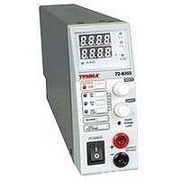
POWER SUPPLY, SWITCH MODE, 16V
Manufacturer
TENMA
Datasheet
1.72-8355.pdf
(11 pages)
Specifications of 72-8355
Power Supply Output Type
Variable
No. Of Outputs
1
Output Voltage
16V
Output Current
5A
Power Rating
80W
Input Voltage
90V AC To 264V AC
Length
330.2mm
Width
50.8mm
Height
127mm
Weight
4.2lb


5. Viewing the Upper Voltage Limit (UVL)
6. Setting the Upper Voltage Limit (UVL) value
7. Master / Slave Operation
Introduction
Two or more Tenma 72-8355 Power Supplies can be connected in parallel to increase output
current to the sum of each supply. In this mode, the designated MASTER supply will control
voltage and current settings of the SLAVE supplies.
Preparation and connecting the Control Terminals (18)
Output terminal connection and operation
•
•
•
•
•
•
•
•
•
•
•
•
•
•
•
•
•
Press UVL/VOLTAGE button (6) to display the default value of Upper Voltage Limit.
The UVL LED (10) will light up during this operation.
This limited access setting utilizes a recessed screwdriver adjustment on the front panel
(3). Note this is a delicate control and care should be exercised when adjustment is made.
While pressing the UVL button (6), insert the small screw driver into (3), slowly turn to
clockwise to increase and counter–clockwise to decrease the UVL value.
Note that only one UVL value can be set for all three ranges. When the output voltage
exceeds the set UVL, the output terminal will automatically turn off and the ALM LED
(13) will illuminate.
Ensure that all power supplies are set to the same UVL (6) and voltage RANGE (8).
Set the voltage and current limit of all SLAVE units to maximum values.
Switch off all power supplies before connection.
Make certain the MASTER supply has switch (17) set in the MASTER position.
Set the switch (17) to SLAVE position of all the SLAVE supplies.
Refer to Fig 8.1 and 8.2 for rear connections of the OUT/IN terminals (18) of the
MASTER and SLAVE units.
Take note that the connection begins at the OUT of the MASTER and feeds the IN of
the first SLAVE unit. If additional SLAVE units are used, connect the OUT of the first
SLAVE, to the IN of the second SLAVE. Then connect the OUT of the second SLAVE
to the IN of the third SLAVE and so on.
You can either use the front OUTPUT terminals (2) or rear O/P+ and O/P– terminals
(20) to connect to the load as shown in Fig 8.3 depending on your application and
requirements.
For proper performance, all power cables should be of the same thickness and length.
Switch on the MASTER unit first and set to desired voltage, then switch on the SLAVE
units.
The SLAVE indicator LED (14) should light up in the SLAVE units as a confirmation
of proper connection.
All output voltage and current of the SLAVE units are now controlled by the MASTER.
7
Related parts for 72-8355
Image
Part Number
Description
Manufacturer
Datasheet
Request
R

Part Number:
Description:
TENMA DESOLDERING STATION, ADJUSTABLE TEMPERATURE: 410-900 DEG F, HEATER: 24 V AT 48 W, WEIGHT: 4.5 LBS, POWER: 110/120 VAC, INCLUDES: IRON HOLDER, GUN TYPE HANDLE, DIMENSIONS: (W X H X D) 8 1/4 X 6 X 6
Manufacturer:
TENMA


Part Number:
Description:
POWER SUPPLY, BENCH, 30V
Manufacturer:
TENMA
Datasheet:
Part Number:
Description:
POWER SUPPLY, BENCH, 30V
Manufacturer:
TENMA
Datasheet:
Part Number:
Description:
POWER SUPPLY, BENCH, 60V
Manufacturer:
TENMA
Datasheet:
Part Number:
Description:
POWER SUPPLY, BENCH, 18V
Manufacturer:
TENMA
Datasheet:

Part Number:
Description:
POWER SUPPLY, BENCH, 30V
Manufacturer:
TENMA
Datasheet:

Part Number:
Description:
POWER SUPPLY, BENCH, 30V/5V
Manufacturer:
TENMA
Datasheet:

Part Number:
Description:
POWER SUPPLY, BENCH, 30V/5V/12V
Manufacturer:
TENMA
Datasheet:

Part Number:
Description:
POWER SUPPLY, BENCH, 30V
Manufacturer:
TENMA
Datasheet:


Part Number:
Description:
Ribbon Cable Assembly, Header To Header, 1 Foot
Manufacturer:
Grayhill Inc
Part Number:
Description:
RS-232 To RS-422/485 Converter With 5V Operation
Manufacturer:
Grayhill Inc
Datasheet: