FPSI 1010 LASCAR, FPSI 1010 Datasheet - Page 4
FPSI 1010
Manufacturer Part Number
FPSI 1010
Description
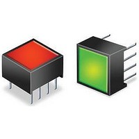
Status Indicator
Manufacturer
LASCAR
Datasheet
1.FPSI_1010.pdf
(4 pages)
Specifications of FPSI 1010
Panel Cutout Height
0.5"
Panel Cutout Width
0.5"
No. Of Pins
8
Length/height, External
10mm
Peak Reflow Compatible (260 C)
No
Accuracy
0.40%
External Width
10mm
Supply Voltage
5V
External Depth
6.2mm
Display Font Color
Red/Green
Leaded Process Compatible
No
Rohs Compliant
Yes
Lead Free Status / RoHS Status
Lead free / RoHS Compliant


FPSI 1010
Specifications liable to change without prior warning
APPLICATIONS
Note: If the FPSI 1010 module is configured for flashing mode, then the relevant RED1, GREEN and RED2
outputs will also pulse High and Low (see Flashing Mode Timing section of this datasheet).
Bottom View
Taking any input beyond the power supply rails will damage the FPSI 1010.
of 2N7000
power supply
4.75 to 5.5V
input voltage
power supply
5.0V
input voltage
power supply
4.75 to 5.5V
input voltage
power supply
4.75 to 5.5V
input voltage
D G S
Input
Consult the MOSFET datasheet for maximum drain current.
{
{
{
{
{
{
{
{
(Module pin-out shown top view)
1
2
3
4
1
2
3
4
1
2
3
4
1
2
3
4
FPSI 1010
V+
0V
Vin
STORE
V+
0V
Vin
STORE
V+
0V
Vin
STORE
V+
0V
Vin
STORE
FPSI 1010
FPSI 1010
FPSI 1010
FPSI 1010
S
GREEN
GREEN
GREEN
GREEN
RED2
RED1
RED2
RED1
RED2
RED1
RED2
RED1
Vref
Vref
Vref
Vref
www.lascarelectronics.com
8
7
6
5
8
7
6
5
8
7
6
5
8
7
6
5
FPSI 1010
1K
1K
V+
/
/
OPTO-ISOLATOR
Basic operation
The indicator is - red when the Vin voltage is between 0V and V1
Switching between measurement ranges
When S is open, the measurement range is 2.5Vd.c.
When S is closed, the measurement range is 5Vd.c.
5
5
RELAY
COIL
2N7000
or equivalent
2N7000
or equivalent
Issue 6
V+
0V
0V
0V
November/2006
- green when the Vin voltage is between V1 and V2
- red when the Vin voltage is between V2 and V+
TO TRIAC
FIRING
CIRCUIT
2 Colour Voltage Level Indicator
Driving a Relay
One of the 3 outputs is shown
driving a relay.
Pins 5, 6 and 7 must not be
allowed to source more than 1mA.
Driving a Triac
One of the 3 outputs is shown
driving a triac.
Pins 5, 6 and 7 must not be
allowed to source more than 1mA.
IRCN
M.C.
: 716 - Page 4 of 4
Applies to FPSI 1010/1
Output 1
Output 2
Output 3
Related parts for FPSI 1010
Image
Part Number
Description
Manufacturer
Datasheet
Request
R

Part Number:
Description:
Status Indicator
Manufacturer:
LASCAR
Datasheet:

Part Number:
Description:
Device Programmer
Manufacturer:
LASCAR
Datasheet:

Part Number:
Description:
Voltage Meter
Manufacturer:
LASCAR
Datasheet:


Part Number:
Description:
DPM, LED, 3.5DIGIT
Manufacturer:
LASCAR
Datasheet:

Part Number:
Description:
Voltage Meter
Manufacturer:
LASCAR
Datasheet:

Part Number:
Description:
DPM, LCD, 3.5DIGIT, NEGATIVE RAIL
Manufacturer:
LASCAR
Datasheet:

Part Number:
Description:
Status Indicator
Manufacturer:
LASCAR
Datasheet:

Part Number:
Description:
Power Supply, Benchtop, 1.5 - 30Vdc (0-1 Amp)
Manufacturer:
Lascar Electronics
Datasheet: