FPSI-PROG LASCAR, FPSI-PROG Datasheet
FPSI-PROG
Manufacturer Part Number
FPSI-PROG
Description
Device Programmer
Manufacturer
LASCAR
Datasheet
1.FPSI-PROG.pdf
(1 pages)
Specifications of FPSI-PROG
Ic Product Type
Programmer
Supported Families
FPSI
Programmer Type
Hardware - Universal
Mcu Supported Families
FPSI
Leaded Process Compatible
Yes
For Use With
FPSI Panel Mount Indicators
Lead Free Status / RoHS Status
Lead free / RoHS Compliant
FPSI 1010 PROG
LASCAR ELECTRONICS LTD.
MODULE HOUSE,
WHITEPARISH,
WILTSHIRE SP5 2SJ,
UK
TEL: +44 (1794) 884567
FAX: +44 (1794) 884616
E-MAIL: sales@lascar.co.uk
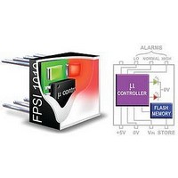
This unit allows you to program the 2 levels on the FPSI 1010.
The unit is powered by an internal 9V (PP3) battery. A ZIF
socket ensures easy insertion and extraction of the module to
be programmed.
FEATURES
OPERATING INSTRUCTIONS
1
- Ensure the Power switch is in the OFF position.
- Ensure the lever on the FPSI socket is vertical.
- Slide the input voltage selector switch to SET V1.
2
- Plug the FPSI module into the topmost section of the FPSI 1010 PROG socket,
- Push the lever on the FPSI socket forwards until it is horizontal.
- Slide the Power switch to the ON position.
3
- Apply the level 1 voltage to the red and black V1 sockets (see drawing).
- Press the PROG switch once.
- The FPSI module flashes Green to indicate that the V1 level has been stored.
4
- Apply the level 2 voltage to the red and black V2 sockets (see drawing).
- Slide the input voltage selector switch to SET V2.
- Press the PROG switch once.
- The FPSI module flashes Red to indicate that the V2 level has been stored.
5
- To enter solid LED mode, make sure V2 does not change, then press the PROG switch once.
- To enter flashing LED mode, change V2 by 100mV or more, then press the PROG switch once.
- The module flashes red or green to indicate that the display mode has been stored.
6
- Slide the Power switch to the OFF position.
- Pull the lever on the FPSI socket upwards and backwards until it is vertical.
- Remove the FPSI module.
The FPSI module is now ready for use.
SAFETY
To comply with the Low Voltage Directive (LVD 93/68/EEC), input voltages to the module’s pins must not exceed
60Vdc. The user must ensure that the incorporation of the panel meter into the user’s equipment conforms to the
relevant sections of BS EN 61010 (Safety Requirements for Electrical Equipment for Measuring, Control and
Laboratory Use).
Specifications liable to change without prior warning
• Compatible with FPSI 1010
• Battery Powered (internal 9V PP3)
• Easy to Set up and Use
• ZIF Socket
with the white dot on the left hand side of the FPSI module.
E-MAIL: us-sales@lascarelectronics.com
www.lascarelectronics.com
LASCAR ELECTRONICS INC.
4258 WEST 12th STREET,
FAX: +1 (814) 838 8141
TEL: +1 (814) 835 0621
PA 16505,
ERIE,
USA
FPSI 1010 PROG
ORDERING INFORMATION
Voltage Level Indicator
Programming Unit
Apply V1
(3Vdc max)
Issue 5
SET V1
OFF ON
Power
switch
FPSI 1010 EVAL
V1
1
to -ve input
No: 732 - Page 1 of 1
UNIT NOS. 6-8, 19/F FUTURA PLAZA,
LASCAR ELECTRONICS (HK) LIMITED
April/2008
Programming Unit
E-MAIL:
PROG
V2
SET V2
111-113 HOW MING STREET,
Stock Number
FPSI 1010
FPSI 1010 PROG
KWUN TONG, KOWLOON,
purchasing@lascar.com.hk
Programming
FAX: +852 2389 6535
TEL: +852 2389 6502
switch
Apply V2
(3Vdc max)
HONG KONG
-ve input
FPSI
Socket
Input
voltage
selector
switch
S.C.
Related parts for FPSI-PROG
Image
Part Number
Description
Manufacturer
Datasheet
Request
R

Part Number:
Description:
Status Indicator
Manufacturer:
LASCAR
Datasheet:

Part Number:
Description:
Status Indicator
Manufacturer:
LASCAR
Datasheet:

Part Number:
Description:
Voltage Meter
Manufacturer:
LASCAR
Datasheet:


Part Number:
Description:
DPM, LED, 3.5DIGIT
Manufacturer:
LASCAR
Datasheet:

Part Number:
Description:
Voltage Meter
Manufacturer:
LASCAR
Datasheet:

Part Number:
Description:
DPM, LCD, 3.5DIGIT, NEGATIVE RAIL
Manufacturer:
LASCAR
Datasheet:

Part Number:
Description:
Status Indicator
Manufacturer:
LASCAR
Datasheet:

Part Number:
Description:
Power Supply, Benchtop, 1.5 - 30Vdc (0-1 Amp)
Manufacturer:
Lascar Electronics
Datasheet: