PD3-109-57-RS TRINAMIC, PD3-109-57-RS Datasheet - Page 2
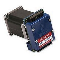
PD3-109-57-RS
Manufacturer Part Number
PD3-109-57-RS
Description
STEPPER MOTOR, PANDRIV, 57MM, 1.63NM
Manufacturer
TRINAMIC
Datasheet
1.PD3-109-57-RS.pdf
(16 pages)
Specifications of PD3-109-57-RS
Torque Max
1.63N-m
Current Rating
3A
No. Of Phases
2
External Depth
57mm
External Length / Height
78.5mm
External Width
57mm
Holding Torque
1.63N-m
Steps Per Revolution
RoHS Compliant
Coil Type
Bipolar
Svhc
No SVHC (15-Dec-2010)
Rohs Compliant
Yes


PD-109-57 / TMCM-109-57 Manual (V1.07 / Jul 18th, 2006)
Contents
1
2
3
4
5
6
7
8
List of Figures
Figure 3.1: Dimensions of base PCB ...................................................................................................... 5
Figure 3.3 Front view of PANDrive.......................................................................................................... 6
Figure 3.4 Side and rear view of PANDrive (108mm refers to PD3 motor) ............................................ 6
Figure 3.5: The TMCM-109 module and its connectors.......................................................................... 7
Figure 4.1: Step, Direction and Disable Inputs...................................................................................... 10
Figure 4.2: Example for Step, Direction and Disable inputs.................................................................. 10
Figure 5.1: Main parts of the TMCM-109 .............................................................................................. 11
Figure 5.2: Step and Direction Signal.................................................................................................... 13
List of Tables
Table 1.1: Order codes............................................................................................................................ 3
Table 3.1: Connector 1 ............................................................................................................................ 7
Table 3.2: Connector 2 ............................................................................................................................ 8
Table 4.1: Operational Ratings................................................................................................................ 9
Table 5.1: Motor Current Examples ...................................................................................................... 13
Table 7.1: Documentation Revisions..................................................................................................... 16
Table 7.2: Firmware Revisions.............................................................................................................. 16
Copyright © 2006, TRINAMIC Motion Control GmbH & Co. KG
3.1
3.2
3.3
3.4
4.1
5.1
5.2
5.3
5.4
5.5
5.6
5.7
5.8
5.9
5.10
7.1
7.2
Features ........................................................................................................................................... 3
Life support policy ............................................................................................................................ 4
Electrical and Mechanical Interfacing............................................................................................... 5
3.1.1
3.1.2
3.3.1
3.3.2
Operational Ratings ......................................................................................................................... 9
Functional Description.................................................................................................................... 11
5.1.1
5.1.2
5.1.3
5.1.4
5.6.1
5.6.2
Putting the TMCM-109 into Operation ........................................................................................... 15
Revision History ............................................................................................................................. 16
References ..................................................................................................................................... 16
Dimensions ............................................................................................................................... 5
Connectors................................................................................................................................ 6
Connecting the Module ............................................................................................................. 7
Connecting the Motor (Connector 3 and 4) .............................................................................. 8
Step, Direction and Disable Inputs.......................................................................................... 10
System Architecture................................................................................................................ 11
Power Supply Requirements .................................................................................................. 12
Disable .................................................................................................................................... 12
Communication Interface – RS232 and RS485...................................................................... 12
Motor Current setting .............................................................................................................. 13
Step / Direction Interface ........................................................................................................ 13
Reference Switches ................................................................................................................ 14
StallGuard™ - Sensorless Motor Stall Detection.................................................................... 14
Environment Temperature Considerations ............................................................................. 14
LEDs ....................................................................................................................................... 14
Documentation Revision ......................................................................................................... 16
Firmware Revision .................................................................................................................. 16
PCB Dimensions.................................................................................................................. 5
PANDrive Dimensions ......................................................................................................... 6
Connector 1: Power Supply, RS485, Step/Direction ........................................................... 7
Connector 2: RS232 and additional I/O ............................................................................... 8
Microcontroller (µC) ........................................................................................................... 11
TMCL EEPROM................................................................................................................. 11
TMC428 Motion Controller................................................................................................. 11
TMC249 Motor Driver ........................................................................................................ 11
Direction Input.................................................................................................................... 13
Step Input........................................................................................................................... 13
2
Related parts for PD3-109-57-RS
Image
Part Number
Description
Manufacturer
Datasheet
Request
R

Part Number:
Description:
57mm / NEMA23 Stepper Motor with Controller / Driver and Serial Interface
Manufacturer:
TRINAMIC [TRINAMIC Motion Control GmbH & Co. KG.]
Datasheet:
Part Number:
Description:
57mm/NEMA23 or 60mm/NEMA24 Stepper Motor with Controller/Driver with Encoder and Serial Interface
Manufacturer:
TRINAMIC [TRINAMIC Motion Control GmbH & Co. KG.]
Datasheet:
Part Number:
Description:
60mm/NEMA24 Stepper Motor with Controller/Driver, with Encoder and Serial Interface
Manufacturer:
TRINAMIC [TRINAMIC Motion Control GmbH & Co. KG.]
Datasheet:
Part Number:
Description:
42mm/NEMA17 Stepper Motor with Controller/Driver, Encoderand Serial Interface
Manufacturer:
TRINAMIC [TRINAMIC Motion Control GmbH & Co. KG.]
Datasheet:
Part Number:
Description:
42mm/NEMA17 High Performance BLDC Motor with Controller/Driver and Serial Interface
Manufacturer:
TRINAMIC [TRINAMIC Motion Control GmbH & Co. KG.]
Datasheet:
Part Number:
Description:
42mm / NEMA17 Stepper Motor with Controller / Driver and Serial Interface
Manufacturer:
TRINAMIC [TRINAMIC Motion Control GmbH & Co. KG.]
Datasheet:
Part Number:
Description:
57mm diameter BLDC Encoder Motor with Controller/Driver and Serial Interface
Manufacturer:
TRINAMIC [TRINAMIC Motion Control GmbH & Co. KG.]
Datasheet:

Part Number:
Description:
2.54mm Pitch Power Board To Boardconnector
Manufacturer:
DDK Ltd.
Datasheet:
Part Number:
Description:
28mm Nema11 Stepper Motor With Controller Driver Serial Interface
Manufacturer:
ETC-unknow
Datasheet:
Part Number:
Description:
3-way Wilkinson Power Divider
Manufacturer:
Marki Microwave
Datasheet:
Part Number:
Description:
3-way Wilkinson Power Divider
Manufacturer:
Marki Microwave
Datasheet: