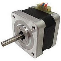
103H5205-5140 SANYO DENKI - SANMOTION, 103H5205-5140 Datasheet - Page 13

103H5205-5140
Manufacturer Part Number
103H5205-5140
Description
Stepper Motor
Manufacturer
SANYO DENKI - SANMOTION
Datasheet
1.BS1D200P10.pdf
(64 pages)
Specifications of 103H5205-5140
No. Of Phases
Two
Inductance
23.4mH
Inertia
0.2oz-in
Step Resolution
1.8°
Peak Reflow Compatible (260 C)
No
Supply Voltage
24VDC
Current Rating
0.5A
Nema Size
17
Leaded Process Compatible
No
Shaft Configuration
Bipolar
Rohs Compliant
Yes
Lead Free Status / RoHS Status
Lead free / RoHS Compliant
■
When it selects the step angle, the driving current is selected, and stops the
current is selected, set by combining rotary switch (RSW) and mode change
switch (PSW).
1. Step angle select(S.S)
The divisions of the basic step angle (0.9
be set with this rotary switch.
Ex-factory setting is at 1 (division 2)
※
2. Driving current select(RUN)
The Motor operation current value can be selected with this rotary switch.
Ex-factory setting is at 0 (rated value).
※
3. Current Select when Stop (STP)
The motor current value when stop and when power down input signal ON
(power low function is selected by dip switch) can be selected with this rotary
switch.
Ex-factory setting is set at A (50%).
※
The slave bureau address of serial communications is set with this rotary
switch.
Ex-factory setting is set at 0
※
◎
◎
Gradation
Partition
Gradation
Partition
Gradation
Motor
current (%)
Gradation
Motor
current
(%)
Gradation
Motor
current (%)
Gradation
Motor
current (%)
(built-in photo coupler ON) of Input/Output signal connector (CN2).
The step angle select switch (S.S) and the number of partitions become invalid by EXT input signal ON
When there is a sufficient extra motor torque, lowering the operation current value will be effective in
the lower vibration. The Motor output torque is almost proportional to the current value. When adjusting
the operational torque, confirm the sufficient operation margin and determine the Motor current value.
The current setting when stop by STP becomes valid when the Motor stops (approximately 200ms after
the last pulse input) and when power down input signal
The slave station address of the pulse stream I/F mode is fixed at 0.
RSW
For pulse stream I/F mode
For parallel I/F mode and serial I/F mode
)
Rotary switch(RSW) and the mode change switch(PSW)
:
0
1
E
F
(rated)
(rated)
100
100
Slave station address (HEX)
25
60
60
0
1
8
0
8
0
8
40
95
55
95
55
1
2
9
1
9
1
9
:
0
1
E
F
2.5
50
90
50
90
50
A
A
A
2
2
2
80
85
45
85
45
B
B
B
3
4
3
3
°
/step) when micro step driving can
100
80
40
80
40
C
C
C
4
5
4
4
125
75
35
75
35
D
D
D
5
8
5
5
200
30
30
10
70
70
6
E
6
E
6
E
250
20
65
25
65
25
7
F
7
F
7
F
12


