D4N3262 Omron, D4N3262 Datasheet - Page 19
D4N3262
Manufacturer Part Number
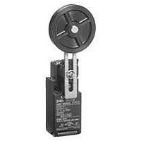
D4N3262
Description
LIMIT SWITCH, ROLLER LEVER, 2NC
Manufacturer
Omron
Type
Limit Switchr
Specifications of D4N3262
Actuator Style
Roller Lever
Operating Force Max
5N
Contact Voltage Ac Max
240V
Contact Voltage Dc Max
250V
Contact Current Ac Max
10A
Contact Current Dc Max
2.5A
Switch Terminals
Screw
Switch Function Configuration
N.C.
Current Rating (max)
3A
Operating Temp Range
-30C to 70C
Lead Free Status / RoHS Status
na


Safety Precautions
Refer to the “Precautions for All Switches” on page I-2 and “Precautions for All Safety Limit Switches” on page B-2.
■ Precautions for Safe Use
• Do not drop the Switch. Doing so may result in the Switch not
• Do not attempt to disassemble or modify the Switch. Doing so may
• Do not use the Switch where explosive gas or flammable gas may
• Do not use the Switch submerged in oil or water, or in locations
• Protect the head from foreign material. Subjecting the head to
• Turn the power OFF before wiring. Not doing so may result in
• Install the cover after wiring. Not doing so may result in electric
• Connect a fuse to the Switch in series to protect the Switch from
• Do not switch circuits for two or more standard loads (250 VAC,
• The durability of the Switch is greatly affected by operating
• Be sure to indicate in the machine manufacturer’s instruction
• Check the Switches before use and inspect regularly, replacing
■ Precautions for Correct Use
Environment
• The Switch is intended for indoor use only.
• Do not use the Switch outdoors. Doing so may cause the Switch to
• Do not use the Switch where corrosive gases (e.g., H
• Do not use the Switches in the following locations.
Do not use metal connectors or conduits. If the Switch is
made of resin, damage at the conduit section may cause
electric shock.
performing to its full capacity.
cause the Switch to malfunction.
be present.
continuously subject to splashes of oil or water. Doing so may result
in oil or water entering the Switch interior. (The IP67 degree of
protection specification for the Switch refers to water penetration
while the Switch is submersed in water for a specified period of
time.)
foreign material may result in premature wear or damage to the
Switch. Although the switch body is protected from penetration by
dust or water, the head is not protected from penetration by minute
particles or water.
electric shock.
shock.
short-circuit damage. Use a fuse with a breaking current 1.5 to 2
times larger than the rated current. To conform to EN ratings, use
an IEC60269-compliant 10-A fuse type gI or gG .
3 A) at the same time. Doing so may adversely affect insulation
performance.
conditions. Evaluate the Switch under actual working conditions
before permanent installation and use within a number of switching
operations that will not adversely affect the Switch’s performance.
manual that the user must not attempt to repair or maintain the
Switch and must contact the machine manufacturer for any repairs
or maintenance.
them when necessary. If a Switch is kept pressed for an extended
period of time, the components may deteriorate quickly, and the
Switch may not release.
malfunction.
HNO
and humidity. Doing so may result in damage to the Switch caused
by contact failure or corrosion.
• Locations subject to severe temperature changes
• Locations subject to high temperatures or condensation
• Locations subject to severe vibration
3
, CI
2
) are present or in locations subject to high temperature
!CAUTION
2
S, SO
2
, NH
3
,
Mounting Method
Mounting Screw Tightening Torque
Tighten each of the screws to the specified torque. Loose screws
may result in malfunction of the Switch within a short time.
Switch Mounting
• Mount the Switch using M4 screws and washers and tighten the
• For safety, use screws that cannot be easily removed, or use an
• Secure the Switch with two M4 bolts and washers. Provide studs
Switch Mounting Holes
• Make sure that the dog contacts the actuator at a right angle.
1
2
3
4
5
6
7
47
2.5
screws to the specified torque.
equivalent measure to ensure that the Switch is secure.
with a diameter of 4
inserting into the holes at the bottom of the Switch as shown below
so that the Switch is firmly fixed at four points.
Applying a load to the switch actuator (roller) on a slant may result
in deformation or damage of the actuator or rotary shaft.
0.1
• Locations where the interior of the Protective Door may come
• Locations where the Switch may come into contact with thinner
0.1
2
into direct contact with cutting chips, metal filings, oil, or
chemicals
or detergents
Terminal screw
Cover clamping screw
Head clamping screw
Lever clamping screw
Body clamping screw
Conduit mounting
connection, M12 adaptor
Cap screw
4
5
1
One-conduit Type
Two, M4
20
22
22
0.1
0.1
0.1
4
Height: 4.8 max.
0.05
0.15
dia.
Safety Limit Switch
0.05
0.15
and a height of 4.8 mm max. at two places,
3
6
5.35
0.1
2.5
0.6 to 0.8 N·m
0.5 to 0.7 N·m
0.5 to 0.6 N·m
1.6 to 1.8 N·m
0.5 to 0.7 N·m
1.8 to 2.2 N·m (except 1/2-
14NPT)
1.4 to 1.8 N·m (1/2-14NPT)
1.3 to 1.7 N·m
39
0.1
0.1
Two-conduit Type
Two, M4
D4N
20
22
40
42
42
0.1
0.1
0.1
0.1
0.1
4
Height: 4.8 max.
0.05
0.15
dia.
B-23
7
Related parts for D4N3262
Image
Part Number
Description
Manufacturer
Datasheet
Request
R

Part Number:
Description:
G6S-2GLow Signal Relay
Manufacturer:
Omron Corporation
Datasheet:
Part Number:
Description:
Compact, Low-cost, SSR Switching 5 to 20 A
Manufacturer:
Omron Corporation
Datasheet:
Part Number:
Description:
Manufacturer:
Omron Corporation
Datasheet:
Part Number:
Description:
Manufacturer:
Omron Corporation
Datasheet:
Part Number:
Description:
Manufacturer:
Omron Corporation
Datasheet:
Part Number:
Description:
Manufacturer:
Omron Corporation
Datasheet:
Part Number:
Description:
Manufacturer:
Omron Corporation
Datasheet:
Part Number:
Description:
Manufacturer:
Omron Corporation
Datasheet: