EDT1411-NTC-2307 CAL CONTROLS, EDT1411-NTC-2307 Datasheet - Page 3
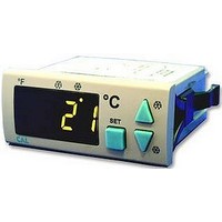
EDT1411-NTC-2307
Manufacturer Part Number
EDT1411-NTC-2307
Description
THERMOSTAT, NTC, 2RELAY, 230VAC
Manufacturer
CAL CONTROLS
Datasheet
1.E-TRANSFORMER-127.pdf
(3 pages)
Specifications of EDT1411-NTC-2307
Thermocouple Type
NTC
Operating Temperature Max
50°C
Operating Temperature Min
0°C
Output Voltage Max
250VAC
Accuracy
± 1°C
Approval Bodies
CE
Approval Category
EN61326-1
Lead Free Status / RoHS Status
Lead free / RoHS Compliant


Unit
Sond
A.rE.S.
R.LoL
R.uPL
R.oFF
R.HYS
DrES
C.pon
C.FoS
C.PPn
D.dur
D.int
D.dSP
D.drE
D.Pon
D.dPo
A.LoL
A.uPL
A.dFL
A.HYS
A.SEt
A.dPo
A. rE
A. CP
A. AL
C.Con
C.PPF
A. DE
RE
DE
CP
Al
SE
-
-
-
-
(if
then
timer runs)
d.Pon
Compressor
Compressor
D.dPo
Display resolution ( = no decimal point, = with decimal point.)
Type of buzzer sound ( 16 different warning tones can be selectable. If
Security parameter for menu of alarm control
Security parameter for refrigeration setpoint value
The lower limit of the setpoint.
The upper limit of the setpoint.
The offset value for the refrigeration.
Switch hysteresis for compressor.
Temperature unit
Delay time for the compressor after power is on.
on time for the compressor output in the case of probe failure.
oFF time for the compressor output in the case of probe failure.
Defrosting duration.(If
Interval between defrost cycles.
Delay time for display real temperature after defrost is over.
Defrosting after power is on.( =Defrosting begins when power is on, =Defrosting doesn’t begin when power is on.)
Delay time for defrosting after power is on.
Limit for upper alarm level.
Time delay to display alarm message after power is on.
Security parameter for refrigeration menu
Security parameter for menu of compressor control
Security parameter for menu of defrost control
Delay time required for the compressor to restart following a stop.
Limit for lower alarm level.
Time delay to display alarm message after alarm is on.
Switch hysteresis for alarm.
Alarm configuration (
A.uPl A.HYS
Continuous-on mode duration for the compressor.
Display configuration during defrost (
d.dPo
A.LoL A.HYS
Menu of Compressor control parameters
SET+ r.HYS
Menu of Refrigeration control parameters
Menu of Defrost control parameters
Menu of Parameter security
Menu of Alarm control parameters
Output
Power
Defrost
A.dPo
=
Alarm
status
D.int
D.dur
-
A.dFL
C.Con
+
NOTE : Variables for lower and upper alarm level are determined according to
A.uPl
LED
y
LED
A.LoL
,
SET
C.Pon
If
A.SEt
=
n
A.rEF
Defrost mode
A.rEF
A.Abs
d.dur
, then
y
= Absolute alarm. Alarm values are
= Relative alarm. Alarm values are
A.LoL
=0, then defrost is disable.)
dEF dEF
= SET-
EDT1411 OUTPUT AND PARAMETER TABLE
rEAL
=
(NonE
ALoL
y
(NonE
= Real temperature is displayed during defrost.
(NonE
&
message is displayed during defrost.)
= menu is invisible,
A.uPL
(
P.yes
(NonE
= menu is invisible,
= menu is invisible,
= SET+
= Setpoint value is invisible.,
= menu is invisible,
A.uPL
.
P.yes
SET A.LoL
A.LoL
P.yes
n
P.yes
AHi enable
A.SEt
-
Sond
= Parameters of menu are changeable,
and
3/3
P.yes
= Parameters of menu are changeable,
parameter. If
=0, then warning tone is disable.)
= Parameters of menu are changeable,
and
A.uPL
AHi
= Parameters of menu are changeable,
SET A.uPL
P.no
dis
.
able
+
A.SEt
= Setpoint value is only visible.)
=
Alo enable
A.AbS
.)
,then
Alo
A.LoL
dis
able
P.no
=
A.LoL
P.no
Continuous mode
P.no
= Parameters of menu are only visible.)
= Parameters of menu are only visible.)
&
P.no
= Parameters of menu are only visible.)
A.uPL
= Parameters of menu are only visible.)
=
A.uPL
.
-50.0
REAL
A.AbS A.rEF
A.LoL
-50.0
R.LoL
-20.0
°C
MÝN
0.1
0
0
0.0
0
0
0
1
0
0
0
0
0
N
0
N
A.uPL
R.uPL
110.0
110.0
20.0
20.0
MAX
DEF
Y
255
255
255
120
255
24.0
255
255
30
255
15
23.5
°F
16
Y
EDT1411-E-06
UNIT DEF.SET
min.
min.
min.
min.
min.
min.
min.
min.
°C
°C
°C
°C
°C
hr.
°C
°C
h.
h.
A.AbS
110.0
-50.0
110.0
DEF
-50.0
0.0
0.1
°C
0.1
1
1
N
2
N
1
1
0
0.3
0
1
1
0
1
Related parts for EDT1411-NTC-2307
Image
Part Number
Description
Manufacturer
Datasheet
Request
R

Part Number:
Description:
THERMOSTAT, NTC, 2RELAY, 12VAC/DC
Manufacturer:
CAL CONTROLS
Datasheet:
Part Number:
Description:
THERMOSTAT, NTC, 2RELAY, 24VAC/DC
Manufacturer:
CAL CONTROLS
Datasheet:

Part Number:
Description:
TEMPERATURE CONTROLLER, RELAY/SSR
Manufacturer:
CAL CONTROLS
Datasheet:

Part Number:
Description:
TEMPERATURE CONTROLLER, RELAY/SSR
Manufacturer:
CAL CONTROLS
Datasheet:

Part Number:
Description:
COMMUNICATION BOARD, RS485
Manufacturer:
CAL CONTROLS
Datasheet:

Part Number:
Description:
PROBE, NTC, PLASTIC SHELL, PVC CABLE
Manufacturer:
CAL CONTROLS
Datasheet:

Part Number:
Description:
PROBE, NTC, THERMOPLASTIC SHELL&CABLE
Manufacturer:
CAL CONTROLS
Datasheet:

Part Number:
Description:
Temperature Controller
Manufacturer:
CAL CONTROLS
Datasheet:

Part Number:
Description:
Temperature Controller
Manufacturer:
CAL CONTROLS
Datasheet:

Part Number:
Description:
TEMPERATURE CONTROLLER, 12VAC/DC
Manufacturer:
CAL CONTROLS
Datasheet:
Part Number:
Description:
TEMPERATURE CONTROLLER, 24VAC
Manufacturer:
CAL CONTROLS
Datasheet:

Part Number:
Description:
TEMP CONTROL, 1XRELAY 100-240V
Manufacturer:
CAL CONTROLS
Datasheet:
Part Number:
Description:
TEMPERATURE CONTROLLER, 2RELAY
Manufacturer:
CAL CONTROLS
Datasheet:

Part Number:
Description:
TEMPERATURE CONTROLLER, 115VAC
Manufacturer:
CAL CONTROLS
Datasheet:
Part Number:
Description:
TEMPERATURE CONTROLLER, 230VAC
Manufacturer:
CAL CONTROLS
Datasheet: