T4820000 Red Lion Controls, T4820000 Datasheet - Page 5
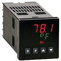
T4820000
Manufacturer Part Number
T4820000
Description
Process/Temperature Controller
Manufacturer
Red Lion Controls
Type
Temperaturer
Datasheet
1.T4810000.pdf
(8 pages)
Specifications of T4820000
Operating Temperature Max
50°C
Operating Temperature Min
0°C
Temperature Accuracy ±
0.3%
Output Voltage Max
7VDC
Output Voltage Min
4V
Controller Input
Thermocouple Or RTD
Brand/series
T48 Series
Dimensions
49.5mmW×49.5mmH×115.3mmD
Enclosure Rating
IP65
Height
1.95 in.
Input Type
RTD/Thermocouple
Ip Rating
IP65
Length
4.17 in.
Memory
EEPROM
Mounting Type
Panel
Output Type
Digital/SSR
Power Consumption
8 VA (Max.)
Power, Rating
8 VA
Primary Type
Controller
Special Features
EEPROM
Standards
cURus, CE
Termination
Screw
Time, Response
400 ms (Max.)
Voltage, Supply
85 to 250 VAC
Width
1.95 in.
Panel Cutout
1.77" × 1.77" (1⁄16 DIN)
Power Requirements
85-250 VAC
Sealing
NEMA 4X/IP65
Operating Temperature
0°C to +50°C
Thermocouple Type
J, K, T, E, R, S, B, N, Linear MV
Rohs Compliant
NA
Lead Free Status / RoHS Status
na


CONTROLLER PROGRAMMING
locked-out from further operator intervention after the initial set-up.
required user-interface level:
UNPROTECTED PARAMETERS MODE *
Mode when program disable is inactive or when the proper access code number
from the Protected Parameter Mode is entered. The Configuration Parameter
Modes can be accessed only from this mode.
PROTECTED PARAMETERS MODE *
This mode prevents access to the Configuration Parameter Modes without the
proper access code number. Only the parameters that are enabled in the
Configuration 3 parameter (lock-out section) can be accessed.
HIDDEN FUNCTION MODE *
The functions in this mode may be locked-out individually in Configuration 3
parameter (lock-out section).
CONFIGURATION PARAMETER MODE
requirements of the controller. It is divided into sections which group together
related programming steps, such as inputs, outputs, alarms, etc. Upon
completion of each section, the program returns to the Configuration Access
Point, allowing the user to return to the Normal Display Mode.
Configuration 1, Inputs (1-IN)
Front Panel Program Disable allows all of the controller’s set-ups to be
The following four programming modes allow the controller to adapt to any
The Unprotected Parameters Mode is accessible from the Normal Display
The Protected Parameters Mode is enabled when program disable is active.
The Hidden Function Mode is accessible from the Normal Display Mode.
The Configuration Parameter Mode allows the operator to set-up the basic
“SP”
“OP”
“ProP”
“Intt”
“dErt”
“AL-1”
“AL-2”
“CNFP”
“End”
“ProP”
“Intt”
“dErt”
“AL-1”
“AL-2”
“CodE”
“SPSL”
“tUNE”
“ALrS”
“tYPE”
“SCAL”
“dCPt”
“FLtr”
“SHFt”
“SPLO”
“SPHI”
“SPrP”
“InPt”
“trnF”
Unprotected Parameter Mode
Protected Parameter Mode
Hidden Function Mode
Configuration Parameter Mode
- Enter setpoint
- Enter output power
- Enter proportional band
- Enter integral time
- Enter derivative time
- Enter value for alarm #1
- Enter value for alarm #2
- Select configuration access point
- Return to normal display mode
- Enter proportional band
- Enter integral time
- Enter derivative time
- Enter value for alarm #1
- Enter value for alarm #2
- Enter value to access unprotected parameters and
- Select local (SP1 or SP2) or remote setpoint
- Transfer between automatic (PID) control and manual control
- Invoke/cancel PID Auto-tune
- Reset latched alarms
- Select input probe type
- Select temperature scale
- Select temperature resolution
- Select level of input filtering
- Enter input correction shift (offset)
- Enter setpoint lower limit
- Enter setpoint higher limit
- Enter setpoint ramp rate
- Select user input function
configuration parameters
5
Configuration 2, Outputs (2-OP) *
Configuration 3, Parameter Lock-Outs (3-LC) *
Configuration 4, Alarms (4-AL) *
Configuration 5, Cooling (5-O2) *
Configuration 6, Serial Communications (6-SC) *
Configuration 7, Remote Setpoint Input (7-N2) *
Configuration 7 - Heater Current Parameters (7-N2) *
Configuration 8, Second Linear DC Analog Output (8-A2) *
Configuration 9, Factory Service Operations (9-FS)
*
These parameters may not appear due to option configuration or other
programming.
“Code 48”
“Code 66”
“bAUd”
“A2LO”
“ConF”
“dSP2”
“bAnd”
“PoPt”
“INP1”
“INP2”
“A2tP”
“A2HI”
“CYCt”
“OPAC”
“OPLO”
“OPHI”
“OPFL”
“OPdP”
“CHYS”
“tcOd”
“ANtP”
“ANAS”
“ANut”
“ANLO”
“ANHI”
“SP”
“OP”
“dEv”
“Hcur”
“UdSP”
“CodE”
“PId”
“AL”
“ALrS”
“SPSL”
“trnF”
“tUNE”
“ACt1”
“rSt1”
“Stb1”
“AL-1”
“ACt2”
“rSt2”
“Stb2”
“AL-2”
“AHYS”
“CYC2”
“GAN2”
“db-2”
“Addr”
“Abrv”
“dSP1”
“Hcur”
“FLtr”
“trnF”
- Select baud rate
- Select character frame format
- Enter address
- Select abbreviated or full transmission
- Select print options
- Enter time proportioning cycle time
- Select output control action
- Enter output power low limit
- Enter output power high limit
- Enter probe fail power preset
- Enter output control dampening
- Enter ON/OFF control hysteresis
- Select auto-tuning dampening
- Main Linear DC analog output range
- Main Linear DC analog output source
- Main Linear DC analog output update time
- Main Linear DC analog output scaling low
- Main Linear DC analog output scaling high
- Select setpoint access level
- Select power access level
- Enable deviation display
- Enable heater current display
- Enable temperature scale display
- Enter parameter access code
- Select PID access level
- Select alarm access level
- Enable alarm reset access
- Enable local/remote selection
- Enable auto/manual mode selection
- Enable auto-tune invocation
- Select operation mode of alarm #1, or select heat output
- Select reset mode of alarm #1
- Enable activation delay of alarm #1
- Enter value for alarm #1
- Select operation mode of alarm #2, or select cooling output
- Select reset mode of alarm #2
- Enable activation delay of alarm #2
- Enter value for alarm #2
- Enter hysteresis value for both alarms
- Enter cooling time proportioning cycle time
- Enter cooling relative gain
- Enter heat/cool deadband or overlap
- Enter remote setpoint display scaling value #1
- Enter remote setpoint process scaling value #1
- Enter remote setpoint display scaling value #2
- Enter remote setpoint process scaling value #2
- Enter remote setpoint filter time constant
- Enter remote setpoint filter disable band
- Select Local/Remote setpoint transfer response
- Enter full scale rating of CT
- Second linear DC analog range
- Second linear DC analog scaling low
- Second linear DC analog scaling high
- Calibrate Instrument
- Reset parameters to factory setting
Related parts for T4820000
Image
Part Number
Description
Manufacturer
Datasheet
Request
R

Part Number:
Description:
Counter
Manufacturer:
Red Lion Controls
Datasheet:
Part Number:
Description:
Miniature Length Sensor
Manufacturer:
Red Lion Controls
Datasheet:
Part Number:
Description:
Model Lsc - Single Channel Output Length Sensor
Manufacturer:
Red Lion Controls
Datasheet: