XF2L-0825-1 Omron, XF2L-0825-1 Datasheet - Page 21
XF2L-0825-1
Manufacturer Part Number
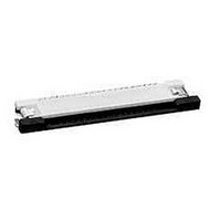
XF2L-0825-1
Description
CONN FPC 8POS 0.5MM SMT
Manufacturer
Omron
Series
XF2Lr
Type
FPC Connectorr
Datasheet
1.XF2L-0725-1.pdf
(28 pages)
Specifications of XF2L-0825-1
Contact Plating
Gold Over Nickel
Connector Type
Top Contacts
Number Of Positions
8
Pitch
0.020" (0.50mm)
Ffc, Fcb Thickness
0.30mm
Height Above Board
0.047" (1.20mm)
Mounting Type
Surface Mount, Right Angle
Cable End Type
Straight
Termination
Solder
Locking Feature
Slide Lock
Features
Zero Insertion Force (ZIF)
Contact Finish
Tin Alloy
Contact Finish Thickness
79µin (2.00µm)
Operating Temperature
-30°C ~ 85°C
Current Rating
0.500A
Voltage Rating
50V
Housing Material
Liquid Crystal Polymer (LCP)
Contact Gender
SKT
Mounting Style
Surface Mount
Number Of Contact Rows
1
Number Of Contacts
8POS
Pitch (mm)
0.5mm
Body Orientation
Right Angle
Contact Resistance Max
30mOhm
Voltage Rating Max
50VDC/50VAC
Operating Temp Range
-30C to 85C
Current Rating (max)
0.5A
Housing Color
Natural
Contact Material
Copper Alloy
Termination Method
Solder
Product Height (mm)
1.2mm
Product Depth (mm)
3.45mm
Product Length (mm)
8.9mm
Gender
Receptacle
Pitch Spacing
0.5mm
No. Of Contacts
8
No. Of Rows
1
Ffc/fpc Thickness
0.3mm
Contact Termination
Surface Mount Vertical
Lead Free Status / RoHS Status
Lead free / RoHS Compliant
Other names
OR680TR
XF2L08251
XF2L08251
Available stocks
Company
Part Number
Manufacturer
Quantity
Price
Company:

Part Number:
XF2L-0825-1
Manufacturer:
OMRON
Quantity:
2 909
Company:
Part Number:
XF2L-0825-1A
Manufacturer:
OMRON
Quantity:
12 000


Common Precautions for XF Connectors
■ Safety Precautions
● All Models
Operating
• Make sure that the FPC has been inserted correctly and
• Insert the FPC fully to the back of the connector. Failing to
• When inserting and removing the FPC, applying pressure
Designing
• Gently pull out the FPC taking care not to apply force
• When installing the FPC at a location or on equipment that
• Use FPCs that conform to the appropriate specifications
• Use the same metal for the FPC plating and the connector
• “Whiskers” may protrude from the FPC film of some lead-
• Ensure a metal mask thickness of t = 0.12 to 0.15 mm.
Mounting
• Do not perform mounting (reflow or manual soldering) with
• The reflow conditions are as stated in OMRON’s specifica-
• When mounting the connector by manual soldering,
XF
1. Conditions for manual soldering: 350±10°C for 3±1
2. Do not apply an excessive amount of solder. Excessive
3. Do not apply the soldering iron to the mount attachments
4. Do not apply the soldering iron to any parts of the
not backward.
Inserting the FPC incorrectly with the FPC connecting face
not aligned with the customer's design specifications may
damage the contacts and equipment may malfunction.
do so may result in a loss of contact reliability.
from above or below, left to right or at an angle may cause
the FPC contacts to become damaged or detached and
may result in contact failure.
directly to the connector.
Bending the FPC in the area where it enters the connector
or applying force to the FPC itself may result in contact fail-
ure.
will subject the FPC to repeated vibration or movement,
secure the FPC prior to use.
and size as stated by OMRON.
When using a different FPC, or an F/F, contact OMRON.
plating.
free FPCs. Be careful when using these units.
The recommended metal mask open area is 90% of the
printed circuit board mating dimensions given in the dimen-
sions diagrams.
the FPC inserted in the connector. Doing so may result in
contact failure.
tions and guidelines. These conditions, however, depend
on the type of solder, the manufacturer, the amount of sol-
der, the size of the circuit board, and the other mounting
materials. Confirm the mounting conditions before using
the connectors.
observe the following precautions to ensure contact reli-
ability.
1. Conditions for manual soldering: 350±10°C for 3±1 s
2. Do not apply an excessive amount of solder. Excessive
3. Do not apply the soldering iron to the mount attach-
4. Do not apply the soldering iron to any parts of the con-
seconds
solder will cause the fl ux to rise.
using force. Doing so may cause the connectors to
change shape.
connector other than the mount attachments. Doing so
may cause the connector to change shape.
solder will cause the flux to rise.
ments using force. Doing so may cause the connectors
to change shape.
nector other than the mount attachments. Doing so may
cause the connector to change shape.
Precautions for Correct Use
Board Mounting Precautions
Board Mounting Precautions
• Be careful of board warping. The connector flatness is
• Be careful of board warping. The connector fl atness is 0.1
• Do not apply excessive force on the connector before
• Do not apply excessive force on the connector before
• Be careful to not apply an excessive load on the board
• Avoid applying excessive force on the board when
1. Dividing multi-cavity boards.
2. Securing a board with screws.
Storage
1. Do not store the connectors in locations subject to dust or
2. Do not store the connectors in locations close to sources
0.1 mm max. A large amount of warping, however, may
result in soldering faults.
mounting it. The connector may be damaged, resulting in
faulty contacts. Do not insert the FPC and lock the slider
before mounting the connector.
when performing the following actions.
1. Dividing multi-cavity boards.
2. Securing a board with screws.
mm max. A large amount of warping, however, may result
in soldering faults.
mounting it. The connector may be damaged, resulting in
faulty contacts. Do not insert the FPC and lock the slider
before mounting the connector.
performing the following actions:”
high humidity.
of gasses such ammonia gas or sulfide gas.
XF
21
Related parts for XF2L-0825-1
Image
Part Number
Description
Manufacturer
Datasheet
Request
R

Part Number:
Description:
CONN FPC 26POS 0.5MM SMT
Manufacturer:
Omron
Datasheet:

Part Number:
Description:
FPC CONNECTOR
Manufacturer:
Omron
Datasheet:

Part Number:
Description:
CONN FPC 4POS 0.5MM PITCH SMD
Manufacturer:
Omron
Datasheet:

Part Number:
Description:
CONN FPC 8POS 0.5MM PITCH SMD
Manufacturer:
Omron
Datasheet:

Part Number:
Description:
CONN FPC 12POS 0.5MM PITCH SMD
Manufacturer:
Omron
Datasheet:

Part Number:
Description:
G6S-2GLow Signal Relay
Manufacturer:
Omron Corporation
Datasheet:
Part Number:
Description:
Compact, Low-cost, SSR Switching 5 to 20 A
Manufacturer:
Omron Corporation
Datasheet:
Part Number:
Description:
Manufacturer:
Omron Corporation
Datasheet:
Part Number:
Description:
Manufacturer:
Omron Corporation
Datasheet:
Part Number:
Description:
Manufacturer:
Omron Corporation
Datasheet:
Part Number:
Description:
Manufacturer:
Omron Corporation
Datasheet: