XF2L-0825-1 Omron, XF2L-0825-1 Datasheet - Page 15
XF2L-0825-1
Manufacturer Part Number
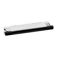
XF2L-0825-1
Description
CONN FPC 8POS 0.5MM SMT
Manufacturer
Omron
Series
XF2Lr
Type
FPC Connectorr
Datasheet
1.XF2L-0725-1.pdf
(28 pages)
Specifications of XF2L-0825-1
Contact Plating
Gold Over Nickel
Connector Type
Top Contacts
Number Of Positions
8
Pitch
0.020" (0.50mm)
Ffc, Fcb Thickness
0.30mm
Height Above Board
0.047" (1.20mm)
Mounting Type
Surface Mount, Right Angle
Cable End Type
Straight
Termination
Solder
Locking Feature
Slide Lock
Features
Zero Insertion Force (ZIF)
Contact Finish
Tin Alloy
Contact Finish Thickness
79µin (2.00µm)
Operating Temperature
-30°C ~ 85°C
Current Rating
0.500A
Voltage Rating
50V
Housing Material
Liquid Crystal Polymer (LCP)
Contact Gender
SKT
Mounting Style
Surface Mount
Number Of Contact Rows
1
Number Of Contacts
8POS
Pitch (mm)
0.5mm
Body Orientation
Right Angle
Contact Resistance Max
30mOhm
Voltage Rating Max
50VDC/50VAC
Operating Temp Range
-30C to 85C
Current Rating (max)
0.5A
Housing Color
Natural
Contact Material
Copper Alloy
Termination Method
Solder
Product Height (mm)
1.2mm
Product Depth (mm)
3.45mm
Product Length (mm)
8.9mm
Gender
Receptacle
Pitch Spacing
0.5mm
No. Of Contacts
8
No. Of Rows
1
Ffc/fpc Thickness
0.3mm
Contact Termination
Surface Mount Vertical
Lead Free Status / RoHS Status
Lead free / RoHS Compliant
Other names
OR680TR
XF2L08251
XF2L08251
Available stocks
Company
Part Number
Manufacturer
Quantity
Price
Company:

Part Number:
XF2L-0825-1
Manufacturer:
OMRON
Quantity:
2 909
Company:
Part Number:
XF2L-0825-1A
Manufacturer:
OMRON
Quantity:
12 000


Rotary Lock Achieves High Reliability and Superior
Work Efficiency.
• Double-sided contact reduces the number of parts.
• Applicable FPC thickness of 0.3 mm.
■ Ratings and Specifications
XF2M-@@15-1A/1AH
■ Dimensions
XF2M-@@15-1@
XF2M-@@15-1@H
Table of Dimensions
Note: Dotted lines refer to the shape and dimensions of models XF2M-5515-1 H
and 6015-1 H.
Note: “H” refers to the shape and dimensions for model series XF2M-5515 and
6015. Please refer to the drawings for more information.
Rated current
Rated voltage
Contact resistance
Insulation resistance 100 M Ω min. (at 250 V DC)
Withstand voltage
Insertion tolerance
Ambient operating
temperature
Pins
(See
note
Rotary Backlock Connector
(0.5-mm Pitch, Double-sided Contact)
(55) XF2M-5515-1@H 27.0 28.1 31.0 31.6 29.6 28.6 32.0
(60) XF2M-6015-1@H 29.5 30.6 33.5 34.1 32.1 31.1 34.5
RoHS Compliant
2.)
10
12
14
18
20
22
24
26
30
32
33
34
35
36
38
40
42
45
50
55
60
XF2M-1015-1@
XF2M-1215-1@
XF2M-1415-1@
XF2M-1815-1@
XF2M-2015-1@
XF2M-2215-1@ 10.5 11.6 14.5 15.1 13.1 12.1 15.5
XF2M-2415-1@ 11.5 12.6 15.5 16.1 14.1 13.1 16.5
XF2M-2615-1@ 12.5 13.6 16.5 17.1 15.1 14.1 17.5
XF2M-3015-1@ 14.5 15.6 18.5 19.1 17.1 16.1 19.5
XF2M-3215-1@ 15.5 16.6 19.5 20.1 18.1 17.1 20.5
XF2M-3315-1@ 16.0 17.1 20.0 20.6 18.6 17.6 21.0
XF2M-3415-1@ 16.5 17.6 20.5 21.1 19.1 18.1 21.5
XF2M-3515-1@ 17.0 18.1 21.0 21.6 19.6 18.6 22.0
XF2M-3615-1@ 17.5 18.6 21.5 22.1 20.1 19.1 22.5
XF2M-3815-1@ 18.5 19.6 22.5 23.1 21.1 20.1 23.5
XF2M-4015-1@ 19.5 20.6 23.5 24.1 22.1 21.1 24.5
XF2M-4215-1@ 20.5 21.6 24.5 25.1 23.1 22.1 25.5
XF2M-4515-1@ 22.0 23.1 26.0 26.6 24.6 23.6 27.0
XF2M-5015-1@ 24.5 25.6 28.5 29.1 27.1 26.1 29.5
(See note 1.)
Model
0.5 A AC/DC
50 V AC/DC
50 m Ω max. (at 20 mV max., 100 mA max.)
250 V AC for 1 min.
20 times
− 30 to 85 ° C
(with no icing or condensation)
(leakage current: 1 mA max.)
A
4.5
5.5
6.5
8.5
9.5 10.6 13.5 14.1 12.1 11.1 14.5
B
5.6
6.6
7.6 10.5 11.1
9.6 12.5 13.1 11.1 10.1 13.5
8.5
9.5 10.1
C
9.1
D
7.1
8.1
9.1
E
6.1
7.1 10.5
8.1 11.5
F
G
9.5
Reference pin mark
0.5
PCB Mating Dimensions (Top View)
±0.05
■ Materials and Finish
XF2M-@@15-1A/1AH
Housing
Slider
Contacts
Hold-down Spring copper alloy/fused-tin plating (1.5 μ m)
0.5
A
F
G
±0.05
E
±0.1
A
B
C
D
±0.1
(See note.)
LCP resin (UL94V-0)/natural
LCP resin (UL94V-0)/black
Spring copper alloy/nickel substrate (2 μ m),
gold-plated contacts (0.15 μ m)
0.25
0.15
(See note.)
±0.05
2.6
1.5
±0.1
±0.1
3.4
1.1
2
(Reinforcement
4.9
board)
4.5
Note: Dotted lines indicate the shape
0.35
0.5
0.5
2.5 min.
Applicable FPC Dimensions
4.88 (See note.)
±0.1
±0.05
±0.03
and dimensions of 55-pin or
60-pin connectors.
6.2 (See note.)
4.62
5.2
XF2M
5.9
(B−0.1)
0.92
(See note.)
±0.05
0.6
2.1
(See
note.)
3.1
T=0.3
(Conductive
plating)
3.2
(See
note.)
1.35
(Effective
interface
length)
±0.05
15
Related parts for XF2L-0825-1
Image
Part Number
Description
Manufacturer
Datasheet
Request
R

Part Number:
Description:
CONN FPC 26POS 0.5MM SMT
Manufacturer:
Omron
Datasheet:

Part Number:
Description:
FPC CONNECTOR
Manufacturer:
Omron
Datasheet:

Part Number:
Description:
CONN FPC 4POS 0.5MM PITCH SMD
Manufacturer:
Omron
Datasheet:

Part Number:
Description:
CONN FPC 8POS 0.5MM PITCH SMD
Manufacturer:
Omron
Datasheet:

Part Number:
Description:
CONN FPC 12POS 0.5MM PITCH SMD
Manufacturer:
Omron
Datasheet:

Part Number:
Description:
G6S-2GLow Signal Relay
Manufacturer:
Omron Corporation
Datasheet:
Part Number:
Description:
Compact, Low-cost, SSR Switching 5 to 20 A
Manufacturer:
Omron Corporation
Datasheet:
Part Number:
Description:
Manufacturer:
Omron Corporation
Datasheet:
Part Number:
Description:
Manufacturer:
Omron Corporation
Datasheet:
Part Number:
Description:
Manufacturer:
Omron Corporation
Datasheet:
Part Number:
Description:
Manufacturer:
Omron Corporation
Datasheet: