K8AB-PH1 Omron, K8AB-PH1 Datasheet - Page 4
K8AB-PH1
Manufacturer Part Number
K8AB-PH1
Description
3-phase Seq Loss Ry.200-500
Manufacturer
Omron
Series
K8ABr
Datasheets
1.K8AB-TH12S_ACDC24.pdf
(8 pages)
2.K8AB-PH1.pdf
(6 pages)
3.K8AB-VS3_100115VAC.pdf
(8 pages)
Specifications of K8AB-PH1
Contact Form
SPDT
Coil Voltage
200 VAC to 500 VAC
Contact Rating
6 A at 250 VAC
Mounting Style
DIN Rail
Lead Free Status / RoHS Status
Lead free / RoHS Compliant
Lead Free Status / RoHS Status
Lead free / RoHS Compliant, Lead free / RoHS Compliant
Other names
K8ABPH1
Z2806
Z2806


Nomenclature
Connections
1. Input
2. Outputs
Dimensions
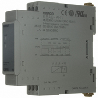
Phase-sequence, Phase-loss Relays
4
K8AB-PH1
Relay status indicator
Connect using L1, L2, and L3.
Make sure the phase sequence is wired correctly. The Unit will not operate normally if the phase
sequence is incorrect.
Terminals 11, 12, and 14 are output terminals for SPDT.
Front
Operation and Setting Methods
Power indicator
Phase-sequence Phase-loss Relay
Terminal block
(See notes 1 and 2.)
K8AB-PH
22.5
Indicators
Note: 1. The input across L1 and L3 is used for the internal power
Power indicator
(PWR: Green)
Relay status indicator
(RY: Yellow)
2. Use either a solid wire of 2.5 mm
3. Tightening torque
Item
supply. Therefore, the power indicator will not be lit if there
is no input across L1 and L3.
insulating sleeve for the terminal connection.
The length of the exposed current-carrying part inserted
into the terminal must be 8 mm or less to maintain dielectric
strength after connection.
Recommended ferrules
Recommended: 0.49 N·m
Maximum: 0.54 N·m
Phoenix Contact
• Al 1,5-8BK (for AWG16)
• Al 1-8RD (for AWG18)
• Al 0,75-8GY (for AWG18)
For 2.5 mm
smaller solid wires
Lit when power is being supplied (see note).
Lit when relay is operating (normally lit).
8 mm max.
100
2
or
72
L1 L2 L3
Load
For ferrules with
insulating sleeves
Meaning
2
Cat. No. N145-E1-02
maximum or a ferrule with
Signal output
Voltage input
8 mm max.
90
5
5
14
12
L1
L2
L3
(Unit: mm)
Relay signal
output
11
Related parts for K8AB-PH1
Image
Part Number
Description
Manufacturer
Datasheet
Request
R

Part Number:
Description:
High Temp 0-1700 C Monitor Rel
Manufacturer:
Omron
Datasheet:

Part Number:
Description:
Low Temp 0-399 C Monitor Relay
Manufacturer:
Omron
Datasheet:

Part Number:
Description:
High Temp 0-1700 C Monitor Rel
Manufacturer:
Omron
Datasheet:

Part Number:
Description:
20-500mA 1-phs Current Monitor
Manufacturer:
Omron
Datasheet:

Part Number:
Description:
20-500mA 1-phs Current Monitor
Manufacturer:
Omron
Datasheet:


Part Number:
Description:
3-phs Voltage Ry. 380-480VAC
Manufacturer:
Omron
Datasheet:


Part Number:
Description:
G6S-2GLow Signal Relay
Manufacturer:
Omron Corporation
Datasheet:
Part Number:
Description:
Compact, Low-cost, SSR Switching 5 to 20 A
Manufacturer:
Omron Corporation
Datasheet:
Part Number:
Description:
Manufacturer:
Omron Corporation
Datasheet: