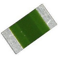
B57421V2103J 62 EPCOS Inc, B57421V2103J 62 Datasheet - Page 10

B57421V2103J 62
Manufacturer Part Number
B57421V2103J 62
Description
NTC Thermistor
Manufacturer
EPCOS Inc
Datasheet
1.B57471V2223J062.pdf
(20 pages)
Specifications of B57421V2103J 62
Thermistor Type
NTC
Resistance
10kohm
Thermistor Tolerance
± 5%
Beta Value (k)
3980K
Thermistor Case Style
0805
No. Of Pins
2
B Constant
±3
Beta Upper Temperature
4000K
Terminal Type
SMD
Dc Resistance Max
10kohm
Rohs Compliant
Yes
Lead Free Status / RoHS Status
Lead free / RoHS Compliant
Mounting instructions
1
1.1
SMD NTC thermistors can be provided with a nickel barrier termination or on special request with
silver-palladium termination. The usage of mild, non-activated fluxes for soldering is recommend-
ed as well as a proper cleaning of the PCB.
The nickel barrier layer of the silver/nickel/tin termination (see figure 1) prevents leaching of the
silver base metalization layer. This allows great flexibility in the selection of soldering parameters.
The tin prevents the nickel layer from oxidizing and thus ensures better wetting by the solder. The
nickel barrier termination is suitable for all commonly-used soldering methods.
Figure 1
SMD NTC thermistors, structure of nickel barrier termination
1.1.1
Preconditioning: Immersion into flux F-SW 32.
Evaluation criterion: Wetting of soldering areas 95%.
Solder
SnPb 60/40
SnAg (3.0 ... 4.0), Cu (0.5 ... 0.9)
1.1.2
Preconditioning: Immersion into flux F-SW 32.
Evaluation criterion: Leaching of side edges 1/3.
Solder
SnPb 60/40
SnAg (3.0 ... 4.0), Cu (0.5 ... 0.9)
Please read Cautions and warnings and
Important notes at the end of this document.
Temperature measurement and compensation
SMD NTC thermistors, case size 0805 (2012)
Nickel barrier termination
Soldering
SMD NTC thermistors
Solderability (test to IEC 60068-2-58)
Resistance to soldering heat (test to IEC 60068-2-58)
Page 10 of 20
Bath temperature ( C)
215 3
245 3
Bath temperature ( C)
260
260
5
5
Dwell time (s)
3
3
Dwell time (s)
10
10
B574**V2


