GXL-8HI PANASONIC EW, GXL-8HI Datasheet - Page 12
GXL-8HI
Manufacturer Part Number
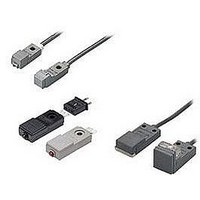
GXL-8HI
Description
Inductive Proximity Sensor
Manufacturer
PANASONIC EW
Datasheet
1.MS-GXL12-2.pdf
(15 pages)
Specifications of GXL-8HI
Sensor Input
Inductive
Sensing Range
1.8mm
Supply Voltage Range Dc
12V To 24V
Lead Free Status / RoHS Status
Lead free / RoHS Compliant


PRECAUTIONS FOR PROPER USE
Mutual interference prevention
Notes: 1) ‘I’ in the model No. specifies the different frequency type.
Sensing range
Correction coefficient
Others
Soldering
GXL-8
type
GXL-N12
type
GXL-15F
GXL-15FU
GXL-15HU
type
GXL-15H
type
GXL-15FLU
GXL-15HLU
type
GXL-15HL
type
Aluminum
Metal
Iron
Stainless
steel
(SUS304)
Brass
Soldering temperature: 260 C
Soldering time
Soldering position
When two or more sensors are installed in parallel or face
to face, keep the minimum separation distance specified
below to avoid mutual interference.
The sensing range is specified for the standard sensing
object. With a non-ferrous metal, the sensing range is
obtained by multiplying with the correction coefficient
specified below. Further, the sensing range also changes
if the sensing object is plated.
Do not use during the initial transient time [10 ms (DC
2-wire type: 50 ms)] after the power supply is switched on.
The output does not incorporate a short-circuit protection
circuit. Do not connect it directly to a power supply or a
capacitive load (excluding the DC 2-wire type).
To solder the terminals of the sensor and connector CN-13,
observe the following conditions.
Model
GXL-N12FT type
CN-13
All models
No.
2) Close mounting is possible for up to two sensors.
When mounting three sensors or more, at an equal spacing, in a
row, the minimum value of dimension H should be as given below.
GXL-8 type: 2 mm
GXL-15 (Standard) type: 7.5 mm
GXL-15 (Long sensing range) type: 30 mm
GXL-8FU
GXL-8HU
type
0.82
approx.
0.59
approx.
0.57
approx.
Between ‘I’ type
and non ‘I’ type
Between two ‘I’ types
or two non ‘I’ types
Between ‘I’ type
and non ‘I’ type
Between two ‘I’ types
or two non ‘I’ types
Between ‘I’ type
and non ‘I’ type
Between two ‘I’ types
or two non ‘I’ types
Between ‘I’ type
and non ‘I’ type
Between two ‘I’ types
or two non ‘I’ types
Between ‘I’ type
and non ‘I’ type
Between two ‘I’ types
or two non ‘I’ types
Between ‘I’ type
and non ‘I’ type
Between two ‘I’ types
or two non ‘I’ types
1
GXL-8F
GXL-8H
type
0.76
approx.
0.50
approx.
0.48
approx.
1
: 5 sec. or less
: 1.5 mm
0.079
(CN-13: 10 sec. or less)
more, away from
the sensor body.
GXL-N12
type
0.70
approx.
0.40
approx.
0.35
approx.
0 mm
(Note 2)
12 mm
0.472 in
0 mm
(Note 2)
20 mm
0.787 in
0 mm
(Note 2)
30 mm
1.181 in
0 mm
(Note 2)
40 mm
1.575 in
0 mm
(Note 2)
75 mm
2.953 in
0 mm
(Note 2)
80 mm
3.150 in
H
1
(GXL-15H type: 12.5 mm
in, GXL-N12 type: 4 mm
500 F
0.059
15 mm
0.591 in
30 mm
1.181 in
15 mm
0.591 in
40 mm
1.575 in
25 mm
0.984 in
60 mm
2.362 in
25 mm
0.984 in
60 mm
2.362 in
25 mm
0.984 in
90 mm
3.543 in
25 mm
0.984 in
95 mm
3.740 in
GXL-15FU
type
0.74
approx.
0.53
approx.
0.52
approx.
J
or less
1
0.295 in
in, or
(GXL-15HL type: 32.5 mm
GXL-15HU
GXL-15FLU
GXL-15HLU
type
Front sensing
Top sensing
0.75
approx.
0.53
approx.
0.51
approx.
1
H
1.181 in
GXL-15F
GXL-15H
type
0.68
approx.
0.47
approx.
0.45
approx.
H
0.157 in
0.492
1
0.059 in
1.5 mm
H
in)
GXL-15HL
type
Soldering
position
0.76
approx.
0.50
approx.
0.48
approx.
J
1.280
1
J
in)
Wiring
Series connection (AND circuit)
Note: The output is generated normally
2-color indicator (Normally open type only)
The sensor must be connected to a power supply via a
load. If the sensor is connected to a power supply without
a load, the short-circuit protection makes the sensor inop-
erable. (The output stays in the OFF state and the indica-
tor does not light up.) In this case, rectify by connecting
the power supply via a load. Now, the sensor becomes
operable. Further, take care that if the power supply is
connected with reverse polarity without a load, the sensor
will get damaged.
For series connection (AND circuit) or parallel connection
(OR circuit) of sensors, take care of the following.
The residual voltage of the sensor is 3 V. Before connect-
ing a relay at the load, take care of its actuation voltage.
(Some 12 V relays may not be usable.)
When the sensing object is in the stable sensing range,
the LED lights up in green, and when the sensing object is
in the unstable sensing range, the LED lights up in red.
While the LED lights up in green, the sensing is performed
stably without being affected by temperature drifts or
voltage fluctuations.
DC 2-wire type
even if the indicator does not light
up properly.
Load
V
RL
Output operation
Max.
operation
distance
V
cc
Brown lead wire
Blue lead wire
2-color indicator operation
When all sensors are in the
ON state, the load voltage
V
V
Make sure that the load
can work properly at
this voltage.
[
RL
RL
Vcc: supply voltage
Blue lead wire
Brown lead wire
is given by:
n: number of sensors
Vcc n 3 (V)
0
( 24 V DC max.)
V
S
V
R
DC
power
supply
3 V Residual voltage
(
Relay actuation
voltage
Refer to
(
when the sensor
is in the ON state
]
Parallel connection (OR circuit)
p.1152l
)
)
Load
LED lights up in red
Unstable range
12 V DC
power supply
I
(I
for general precautions.
cc
L
)
V
Brown lead wire
Blue lead wire
Output operation
level
cc
When all sensors are in the
OFF state, the load leakage
current Icc is given by:
I
(n: number of sensors)
Make sure that the load
can work properly.
Note: The load current in the
I
GXL-8 type :
GXL-15 type :
Relay actuation
voltage:
V
cc
L
3 mA
(
3 mA
(
R
n: number of sensors
n: number of sensors
h 9 V
h 12
turned ON
turned ON
Load resistance
n
GXL
ON state is given by:
Vcc
n h I
n h l
0.8 (mA)
DC
power
supply
3 V
3 V
L
L
695
h
h
100 mA
70 mA
(mA)
)
)
Related parts for GXL-8HI
Image
Part Number
Description
Manufacturer
Datasheet
Request
R

Part Number:
Description:
DC 2-WIRE NO FRONT 5MM
Manufacturer:
PANASONIC EW
Datasheet:
Part Number:
Description:
DC 2-WIRE NO TOP 2.5MM
Manufacturer:
PANASONIC EW
Datasheet:

Part Number:
Description:
Inductive Proximity Sensor
Manufacturer:
PANASONIC EW
Datasheet:

Part Number:
Description:
Inductive Proximity Sensor
Manufacturer:
PANASONIC EW
Datasheet:

Part Number:
Description:
M12 NON-SHIELD DC 2WIRE APPR ON (NO) 3MM 1.2KZ IP67G
Manufacturer:
PANASONIC EW
Part Number:
Description:
M12 NON-SHLD DC 2WIRE APPR ON (NO) 3MM 1.2KHZ IP67G QD
Manufacturer:
PANASONIC EW

Part Number:
Description:
SIGNAL RELAY, DPDT, 5VDC, 2A, PC BOARD
Manufacturer:
PANASONIC EW
Datasheet:


Part Number:
Description:
PHOTOMOS RELAY, 60VDC, 400mA
Manufacturer:
PANASONIC EW
Datasheet:

Part Number:
Description:
PHOTOMOS RELAY, 400V, 150mA
Manufacturer:
PANASONIC EW
Datasheet: