GXL-8HI PANASONIC EW, GXL-8HI Datasheet - Page 11
GXL-8HI
Manufacturer Part Number
GXL-8HI
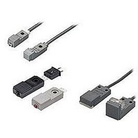
Description
Inductive Proximity Sensor
Manufacturer
PANASONIC EW
Datasheet
1.MS-GXL12-2.pdf
(15 pages)
Specifications of GXL-8HI
Sensor Input
Inductive
Sensing Range
1.8mm
Supply Voltage Range Dc
12V To 24V
Lead Free Status / RoHS Status
Lead free / RoHS Compliant


GXL
PRECAUTIONS FOR PROPER USE
Mounting
<
(
GXL-8 (DC 2-wire) type
GXL-8 (NPN output) type
GXL-N12 type
The tightening torque should
be 0.5 N m or less.
To mount the sensor with a nut,
the thru-hole diameter should be
"3.4 mm
attached mounting screw and
nut, take care that the thickness
of the mounting plate should be
2.3 mm
If a screw other than the
attached screw is used, make
sure to use a M3 truss head
screw.
The tightening torque should
be 0.5 N m or less.
To mount the sensor with a nut,
the thru-hole diameter should
be "3 mm
attached mounting screw and
nut, take care that the thickness
of the mounting plate should be
2.3 mm
If a screw other than the
attached screw is used, make
sure to use a M2.6 truss head
screw.
Do not use a flat head screw
or a pan head screw.
Note: Do not use a M3 screw.
One point fixing
The tightening torque should be 0.49 N m or less.
To mount the sensor with a nut, the thru-hole diameter
should be "3.4 mm
694
All models
This product is not a safety sensor. Its use is not
intended or designed to protect life and prevent body
injury or property damage from dangerous parts of
machinery. It is a normal object detection sensor.
0.091 in
M3 (length 12 mm
pan head screw (Accessory)
0.091 in
If mounting using nut
and washers
(Accessories)
M3 0.5 mm
(Depth: 10 mm
or "3.4 mm
Rubber washer (Accessory)
"0.134
"0.118
"0.134 in
0.020 in
>
or less.
0.394 in
or less.
0.472
tapped hole
in. With the
in. With the
thru-hole
or more)
"0.134
in)
"2.5 mm
(Depth: 3 mm
in.
"0.098 in
0.118 in
)
<
Two point fixing
"2.0 mm
(Depth: 3 mm
"2.4 mm
(Depth: 3 mm
or more)
hole
11.5 mm
11.5 mm
16
0.630
"0.079 in
"0.094 in
M2.6 (length 12 mm
truss head screw
If mounting using nut
and washers
(Accessories)
(Accessory)
If mounting using nut
and washers
(Accessories)
(Accessory)
0.118 in
M3 (length 12 mm
head screw
0.118 in
M3 0.5 mm
(Depth: 8 mm
or "3.4 mm
M2.6 0.45 mm
(Depth: 8 mm
or "3 mm
If mounting using nut
and washers
(Accessories)
(Accessory)
M3 (length 12 mm
pan head screw (Accessory)
0.453 in
MS-GXL8
0.453 in
MS-GXL8-4
(Accessory)
M3 0.5 mm
(Depth: 10 mm
or "3.4 mm
MS-GXL12-1
(Accessory)
or more)
or more)
hole
hole
>
"0.118 in
0.020 in
"0.134 in
0.315 in
"0.134 in
0.315 in
0.018 in
0.020 in
0.394 in
0.472
0.472
tapped hole
0.472
tapped hole
tapped hole
thru-hole
or more)
in) truss
or more)
thru-hole
thru-hole
or more)
in)
in)
Influence of surrounding metal
Note: The GXL-15FLU type should be mounted on an insulator or a non-
Note: When GXL-15HLU / GXL-15HL type is mounted on an insulator or a
GXL-15 type
Front sensing type
Top sensing type
The tightening torque should
To mount the sensor with the
be 1 N m or less.
optional sensor mounting bracket
MS-GXL15, the thru-hole diameter
should be "3.4 mm
Screw, nut or washers are not
supplied. Please arrange them
separately.
To mount the long sensing range
GXL-15 type on a magnetic body,
such as iron, the enclosed
aluminum sheet, or any other
aluminum sheet having a minimum
size of 30
1.181
(GXL-15HLU
30 30
t 0.012
between the sensor and the
magnetic body.
However, it is not necessary to use
the aluminum sheet when
mounting on a non-magnetic body,
such as, aluminum or an insulator.
When mounting the inductive
proximity sensor with the optional
sensor
MS-GXL15-2, if the bracket is
mounted close to the sensing part,
the bracket itself gets sensed and
the operation becomes unstable.
Make sure to mount such that the
mounting holes of the sensor and
those of the mounting bracket are
in one horizontal straight line.
When there is a metal near the sensor, keep the minimum
separation distance specified below.
A
B
C
D
E
G
F
Metal
A
E
magnetic body. To mount it on a magnetic body, such as iron, use the
enclosed aluminum sheet.
non-magnetic body, or seated on the enclosed aluminum sheet, the
distance ‘F’ can be zero.
7 mm
8 mm
3 mm
GXL-8F type
0
10 mm
0
0
GXL-8H type
B
4 mm
3 mm
3 mm
in), should be inserted
0.276 in
0.315 in
0.118 in
1.555
t 0.3 mm
mounting
0.157 in
0.394 in
0.118 in
0.118 in
F
39.5
D
/ GXL-15HL :
1.181 1.181
GXL-N12F type GXL-15FU / GXL-15F type GXL-15FLU type
07 mm
20 mm
10 mm
t 0.012 in
"0.134
Refer to
t 0.3 mm
GXL-15HU / GXL-15H type GXL-15HLU / GXL-15HL type
Metal
bracket
0.276 in
0.787 in
0.394 in
Metal
0
20 mm
0
0
6 mm
0 mm
3 mm
in.
p.1152l
0.236 in
0.787 in
0.118 in
08 mm
20 mm
07 mm
Metal
Sensor’s
mounting
holes
0 in
G
(
MS-GXL15-2
Metal
Optional sensor
mounting bracket
for general precautions.
0.315 in
0.787 in
0.276 in
C
9 mm
0.354 in
10 mm
G
M3 pan head screw
or truss head screw
GXL-15F
(
When mounting using
MS-GXL15 (Optional)
If mounting using nut
and washers.
M3 0.5 mm
or "3.4 mm
Do not use a
flat head screw
12 mm
30 mm
10 mm
Aluminum sheet
C
8 mm
30 mm
10 mm
0.394 in
"0.134 in
0.020 in
Sensor
mounting
bracket’s
mounting
holes
)
0.315 in
0.472 in
1.181 in
0.394 in
1.181 in
0.394 in
tapped hole
)
(Note)
thru-hole
(Note)
Related parts for GXL-8HI
Image
Part Number
Description
Manufacturer
Datasheet
Request
R

Part Number:
Description:
DC 2-WIRE NO FRONT 5MM
Manufacturer:
PANASONIC EW
Datasheet:
Part Number:
Description:
DC 2-WIRE NO TOP 2.5MM
Manufacturer:
PANASONIC EW
Datasheet:

Part Number:
Description:
Inductive Proximity Sensor
Manufacturer:
PANASONIC EW
Datasheet:

Part Number:
Description:
Inductive Proximity Sensor
Manufacturer:
PANASONIC EW
Datasheet:

Part Number:
Description:
M12 NON-SHIELD DC 2WIRE APPR ON (NO) 3MM 1.2KZ IP67G
Manufacturer:
PANASONIC EW
Part Number:
Description:
M12 NON-SHLD DC 2WIRE APPR ON (NO) 3MM 1.2KHZ IP67G QD
Manufacturer:
PANASONIC EW

Part Number:
Description:
SIGNAL RELAY, DPDT, 5VDC, 2A, PC BOARD
Manufacturer:
PANASONIC EW
Datasheet:


Part Number:
Description:
PHOTOMOS RELAY, 60VDC, 400mA
Manufacturer:
PANASONIC EW
Datasheet:

Part Number:
Description:
PHOTOMOS RELAY, 400V, 150mA
Manufacturer:
PANASONIC EW
Datasheet: