SME312D BANNER ENGINEERING, SME312D Datasheet - Page 4
SME312D
Manufacturer Part Number
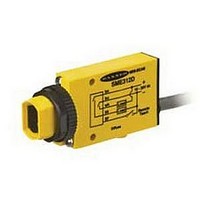
SME312D
Description
Photoelectric Sensor
Manufacturer
BANNER ENGINEERING
Datasheet
1.MQDC1-506.pdf
(12 pages)
Specifications of SME312D
Output Current
150mA
Sensor Output
NPN/PNP
Supply Voltage Range Dc
10V To 30V
Sensor Input
Optical
Output Type
Transistor
Sensing Range Max
380mm
Contact Current Max
150mA
Switch Terminals
Cable


a relative indication of sensing contrast between the light and dark conditions.
Remote Configuration
The remote function may be used to configure the sensor remotely or to disable the
push button for security. Connect the gray wire of the sensor to ground (0V dc), with a
remote programming switch connected between them. Pulse the remote line according to
the diagrams in the configuration procedures. The length of the individual programming
pulses is equal to the value T:
Troubleshooting
The MINI-BEAM Expert’s Power LED may begin to alternate flashing red/green; this
indicates a microprocessor memory error. If it occurs, try reteaching the sensor, or
try cycling power ON and OFF, then reteaching the sensor. If this does not solve the
problem, or if it occurs frequently, replace the sensor.
Status Indicators
Normal sensor operation is called RUN mode. Sensor configuration (setting the sensitivity
threshold and selecting output ON and OFF conditions) is performed in TEACH mode.
The two LED indicators (bi-color Green/Red and Yellow) have distinct roles in the two
operation modes, as shown in Figure 2.
If contrast is marginal, the bi-color indicator will flash green to indicate instability. If this
occurs, reconfigure or realign the sensor, or clean the sensor or fiber lenses.
The Signal Strength indicator is Banner’s exclusive AID™ (Alignment Indicating
Device). Its pulse rate increases as the received light signal strength increases (during
programming). This feature simplifies accurate alignment during TEACH mode, and gives
Figure 2. Status Indicator Conditions
MINI-BEAM
** The faster the pulse rate, the stronger the light signal.
* This is the Stability indicator, which signals when maintenance, realignment, or reconfiguration is needed
during RUN mode.
P/N 55214 rev. E
ON Green: Power is ON
Flashing Green: Sensed light level is
ON: Outputs conducting
OFF: Outputs not conducting
®
RUN Mode
approaching sensing
threshold*
0.0 seconds ≤ “T” ≤ 0.8 seconds
Expert
™
Series
ON Red: Sensor “sees” its own modulated
ON: Ready to TEACH output ON condition
OFF: Ready to TEACH output OFF
condition
light source; pulse rate is
proportional to the received light
signal strength**
TEACH Mode
Banner Engineering Corp. • Minneapolis, MN U.S.A.
www.bannerengineering.com • Tel: 763.544.3164
Related parts for SME312D
Image
Part Number
Description
Manufacturer
Datasheet
Request
R

Part Number:
Description:
Photoelectric Sensor
Manufacturer:
BANNER ENGINEERING
Datasheet:

Part Number:
Description:
Photoelectric Sensor
Manufacturer:
BANNER ENGINEERING
Datasheet:

Part Number:
Description:
LEDIR70XD4-XM-81039 MAX INTENS STROBE ONLY NO BANNER MARKS
Manufacturer:
BANNER ENGINEERING
Part Number:
Description:
M18SP6DL-72225 LABELED MOELLER NO BANNER MARKINGS BULK PACK
Manufacturer:
BANNER ENGINEERING
Part Number:
Description:
M18SP6DLQ-72226 LABLED MOELLER NO BANNER MARKINGS BULK PACK
Manufacturer:
BANNER ENGINEERING
Part Number:
Description:
M18SP6L-72223 LABELED MOELLER NO BANNER MARKINGS BULK PACK
Manufacturer:
BANNER ENGINEERING
Part Number:
Description:
M18SP6LQ-72224 LABELED MOELLER NO BANNER MARKINGS BULK PACK
Manufacturer:
BANNER ENGINEERING
Part Number:
Description:
P4D1-77908 P4 DRIVER GENERIC NO BANNER MARKINGS RESALE TO CUSTOMER
Manufacturer:
BANNER ENGINEERING
Part Number:
Description:
Photoelectric Sensor
Manufacturer:
BANNER ENGINEERING
Datasheet:

Part Number:
Description:
Programmable Indicator Light
Manufacturer:
BANNER ENGINEERING
Datasheet:
Part Number:
Description:
INDICATOR LED PANEL 50MM GRN/RED/YEL 30V
Manufacturer:
BANNER ENGINEERING
Datasheet:
Part Number:
Description:
Programmable Indicator Light
Manufacturer:
BANNER ENGINEERING
Datasheet: