SM912LV BANNER ENGINEERING, SM912LV Datasheet - Page 7
SM912LV
Manufacturer Part Number
SM912LV
Description
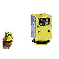
Photoelectric Sensor
Manufacturer
BANNER ENGINEERING
Datasheet
1.SM912LV.pdf
(20 pages)
Specifications of SM912LV
Output Current
250mA
Sensor Output
NPN/PNP
Supply Voltage Range Dc
10V To 30V
Sensing Range Max
9m
Sensor Housing
Rectangular
Switch Terminals
Cable
Sensor Input
Optical
Sensing Mode
Retroreflective


VALU-BEAM 912 Series Sensors
FIBER OPTIC Mode
DIFFUSE
OPPOSED FIBER OPTIC
MODE (glass fibers)
OPPOSED
RETRO
EMITTER
Sensing Mode
RETROREFLECTIVE TARGET
OBJECT
OBJECT
OBJECT
OBJECT
RECEIVER
SM912F
Voltage: 10 to 30V dc
Range: see E.G. curves
Response: 4ms on/off
Beam: infrared, 880nm
Fiber optic sensing is often
the answer when, due to space
or environmental limitations,
the sensor itself cannot be
placed at the actual sensing
position. These sensors' pow-
erful modulated infrared
beam is compatible with all
Banner glass fiber optics in
the opposed, retroreflective,
and diffuse sensing modes
(see Banner product catalog).
Sensor/fiber interface is wa-
terproof to maintain complete
sensing system moisture re-
jection.
SM2A912F
Voltage: 24 to 250V ac
Range: see E.G. curves
Response: 8ms on/off
Beam: infrared, 880nm
Repeatability:
Repeatability:
SMA91EF &
Voltage: 10 to 30V dc
("EF": 10-250V ac/dc)
Range: see E.G. curves
Response: 8ms on/4 off
Beam: infrared, 880nm
SMA91EF &
Voltage: 24 to 250V ac
("EF": 10-250V ac/dc)
Range: see E.G. curves
Response: 8ms on/4 off
Beam: infrared, 880nm
1.3ms (dc models);
2.6ms (ac models)
1.0ms (all models)
Models
SM2A91RF
SM91RF
These opposed mode fiber optic emitter-receiver pairs are used where the
separation between emitting and receiving fibers is greater than a few feet, or
where it is inconvenient to run both fibers from a single VALU-BEAM sensor.
These models have a watertight o-ring sealed sensor/fiber interface, and are
compatible with all Banner glass fiber optic assemblies (see product catalog).
E
X
C
E
S
S
G
A
I
N
I
E
X
C
E
S
S
G
A
I
N
E
X
C
E
S
S
G
A
I
N
I
I
1000
1000
1000
E
X
C
E
S
S
G
A
I
N
100
I
100
100
1000
10
10
10
100
1
.1 IN
.1 FT
.1 IN
1
1
10
.1 FT
1
SM912F, SM2A912F
with
BT13S
fibers
Excess Gain
with
IT13S
fibers
SM912F, SM2A912F
SM912F,
SM2A912F
IT13S fibers
with L9 lens
and BT13S
fibers
1 IN
1 FT
1 IN
with
IT23S
fibers
Range based on 90%
reflectance white test card
with
1 FT
IT23S
DISTANCE
DISTANCE
DISTANCE
and
with
BT23S
fibers
Diffuse mode
L9
lenses
DISTANCE
Retroreflective
mode, w/BRT-3 3"
target
IT23S fibers
10 IN
10 FT
10 IN
with L16F lens
and BT13S
fibers
10 FT
SMA91EF &
SM91RF,
SMA91EF &
SM2A91RF
Opposed
mode,
glass fibers
with
IT23S &
L16F
lenses
100 IN
100 FT
100 IN
100 FT
I
N
C
H
E
S
I
N
C
H
E
S
I
N
C
H
E
S
I
N
C
H
E
S
.075
.050
.025
.025
.050
.075
DISTANCE TO 90% WHITE TEST CARD--INCHES
0
12
0
12
0
8
4
4
8
3
2
1
1
2
3
0
.1
.1
6
4
2
2
4
6
0
0
0
0
opposed mode
Beam Pattern
SMA91EF/SM91RF,
SMA91EF/SM2A91RF
SM912F, SM2A912F
with L9 lens
DISTANCE TO REFLECTOR--FEET
SM912F, SM2A912F
4
.3
4
8
OPPOSED DISTANCE --INCHES
OPPOSED DISTANCE--FEET
IT23S fibers
with L9 lenses
IT13S fibers
SM912F, SM2A912F
Retroreflective mode,
BT13S fiber, BRT-3 reflector
Diffuse mode
8
8
.6
16
IT23S fibers
BT13S
with L16F lens
.9
12
12
IT23S fibers
with L16F lenses
24
16
1.2
16
BT23S
32
20
1.5
20
40
7
Related parts for SM912LV
Image
Part Number
Description
Manufacturer
Datasheet
Request
R

Part Number:
Description:
Photoelectric Sensor
Manufacturer:
BANNER ENGINEERING
Datasheet:

Part Number:
Description:
Photoelectric Sensor
Manufacturer:
BANNER ENGINEERING
Datasheet:

Part Number:
Description:
LEDIR70XD4-XM-81039 MAX INTENS STROBE ONLY NO BANNER MARKS
Manufacturer:
BANNER ENGINEERING
Part Number:
Description:
M18SP6DL-72225 LABELED MOELLER NO BANNER MARKINGS BULK PACK
Manufacturer:
BANNER ENGINEERING
Part Number:
Description:
M18SP6DLQ-72226 LABLED MOELLER NO BANNER MARKINGS BULK PACK
Manufacturer:
BANNER ENGINEERING
Part Number:
Description:
M18SP6L-72223 LABELED MOELLER NO BANNER MARKINGS BULK PACK
Manufacturer:
BANNER ENGINEERING
Part Number:
Description:
M18SP6LQ-72224 LABELED MOELLER NO BANNER MARKINGS BULK PACK
Manufacturer:
BANNER ENGINEERING
Part Number:
Description:
P4D1-77908 P4 DRIVER GENERIC NO BANNER MARKINGS RESALE TO CUSTOMER
Manufacturer:
BANNER ENGINEERING
Part Number:
Description:
Photoelectric Sensor
Manufacturer:
BANNER ENGINEERING
Datasheet:

Part Number:
Description:
Programmable Indicator Light
Manufacturer:
BANNER ENGINEERING
Datasheet:
Part Number:
Description:
INDICATOR LED PANEL 50MM GRN/RED/YEL 30V
Manufacturer:
BANNER ENGINEERING
Datasheet:
Part Number:
Description:
Programmable Indicator Light
Manufacturer:
BANNER ENGINEERING
Datasheet: