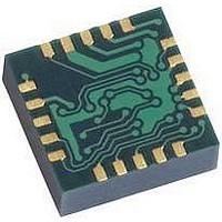
HMC5843 Honeywell Microelectronics & Precision Sensors, HMC5843 Datasheet - Page 8

HMC5843
Manufacturer Part Number
HMC5843
Description
Magnetic Sensor
Manufacturer
Honeywell Microelectronics & Precision Sensors
Datasheet
1.HMC5843.pdf
(21 pages)
Specifications of HMC5843
Msl
MSL 3 - 168 Hours
Sensitivity Range
+/- 10 %
Sensor Terminals
PCB
Magnetic Field Max
4G
Axis Configuration
Three
Sensor Output
Digital
Available stocks
Company
Part Number
Manufacturer
Quantity
Price
Company:
Part Number:
HMC5843
Manufacturer:
HITTITE
Quantity:
3 000
Company:
Part Number:
HMC5843-DEMO
Manufacturer:
Honeywell Microelectronics & P
Quantity:
135
Company:
Part Number:
HMC5843-EVAL
Manufacturer:
Honeywell Microelectronics & P
Quantity:
135
HMC5843
ASIC Turn-On Times
The table below shows the turn-on time for individual functions within this ASIC.
Voltage Regulator
This ASIC has an internal voltage regulator which, depending on the application needs, may be used instead of supplying
voltage to pin DVDD. If DVDD pin is used, the internal voltage regulator is not engaged. When both supplies are used,
DVDD is typically high before AVDD, but no latch-up conditions will exist if DVDD is brought high after AVDD.
Power on Reset
Power on reset (POR) circuit shall return the device to the power-on default state. All registers shall be returned to their
default values. Circuitry shall return to it default state, such as, but not limited to: MUX channel, ADC state machine, and
bias current.
I
Control of this device is carried out via the I
control of a master device, such as the processor.
This device shall be compliant with I
device, this device has a 7-bit serial address and supports I
modes, 100kHz and 400kHz respectively, but cannot support the high speed mode (Hs). External pull-up resistors are
required to support these standard and fast speed modes. Depending on the application, the internal pull-ups may be
used to support slower data speeds than specified by I
suppression as required by fast mode operation in the I
SCL I/O stages for F/S-mode I
Activities required by the master (register read and write) have priority over internal activities, such as the measurement.
The purpose of this priority is to not keep the master waiting and the I
I
Pull-up resistors are placed on the two I
in specific low clock speed applications, they are internal to this device.
Internal Clock
The device has an internal clock for internal digital logic functions and timing management.
H-Bridge for Set/Reset Strap Drive
The ASIC contains large switching FETs capable of delivering a large but brief pulse to the Set / Reset strap of the
sensor. This strap is largely a resistive load.
8
2
2
C Interface
C Pull-up Resistors
Parameter
Clock Turn-on
Logic Turn-on
Analog Turn-on
Voltage Regulator Turn-
on
2
C-bus devices”.
Sym.
t
t
t
t
CLK_ON
LOG_ON
ANL_N
VR_ON
2
C-Bus Specification, document number: 9398 393 40011. As an I
2
C bus lines. Typically these resistors are off-chip, but, to conserve board space
Condition
Stabilized
Register values and DRDY pin
defined
Includes ADC, Amplifier, MUX.
Capable of completing an ADC
conversion within specifications.
Enabled and stable
2
C bus. This device will be connected to this bus as a slave device under the
Table 3: Turn-On Times
2
C-Bus Specification, “Table 4 Characteristics of the SDA and
2
C standards. This device does not contain 50nsec spike
2
C protocols. This device shall support standard and fast
2
C bus engaged for longer than necessary.
Min
Typ
Max
4.5
0.5
0.5
5
www.honeywell.com
Units
ms
ms
ms
ms
2
C compatible


