SHT21 SENSIRION, SHT21 Datasheet - Page 8
SHT21
Manufacturer Part Number
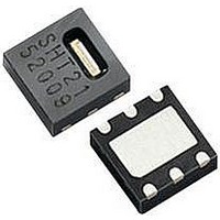
SHT21
Description
Humidity/Temperture Sensor
Manufacturer
SENSIRION
Datasheet
1.SHT21.pdf
(12 pages)
Specifications of SHT21
Operating Temperature Range
-40°C To +125°C
No. Of Pins
6
Supply Voltage
3V
Humidity Sensor Type
Capacitive
Sensor Case Style
DFN
Humidity Range
0% To 100%
Response Time
8s
Accuracy
± 2%
Supply Current
300µA
Available stocks
Company
Part Number
Manufacturer
Quantity
Price

Part Number:
SHT21
Manufacturer:
SENSIRION
Quantity:
20 000


Datasheet SHT21
5.4
There are two different operation modes to communicate
with the sensor: Hold Master mode or No Hold Master
mode. In the first case the SCL line is blocked (controlled
by sensor) during measurement process while in the latter
case the SCL line remains open for other communication
while the sensor is processing the measurement. No hold
master
communication tasks on a bus while the sensor is
measuring. A communication sequence of the two modes
is displayed in Figure 15 and Figure 16, respectively.
In the hold master mode, the SHT2x pulls down the SCL
line while measuring to force the master into a wait state.
By releasing the SCL line the sensor indicates that internal
processing is terminated and that transmission may be
continued.
Figure 15 Hold master communication sequence – grey blocks
are controlled by SHT2x. Bit 45 may be changed to NACK
followed by Stop condition (P) to omit checksum transmission.
In no hold master mode, the MCU has to poll for the
termination of the internal processing of the sensor. This is
done by sending a Start condition followed by the I
header (1000’0001) as shown in Figure 16. If the internal
processing is finished, the sensor acknowledges the poll of
the MCU and data can be read by the MCU. If the
measurement processing is not finished the sensor
answers no ACK bit and the Start condition must be
issued once more.
For both modes, since the maximum resolution of a
measurement is 14 bit, the two last least significant bits
(LSBs, bits 43 and 44) are used for transmitting status
information. Bit 1 of the two LSBs indicates the
measurement type (‘0’: temperature, ‘1’ humidity). Bit 0 is
currently not assigned.
www.sensirion.com
S 1 0 0 0 0 0 0 1
S 1 0 0 0 0 0 0 0
28 29 30 31 32 33 34 35 36 37 38 39 40 41 42 43 44 45
19 20 21 22 23 24 25 26 27
0 1 1 0 0 0 1 1
Data (MSB)
46 47 48 49 50 51 52 53 54
0 1 1 0 0 0 1 1
1
2
I
I
Hold / No Hold Master Mode
2
2
C address + write
C address + read
3
Checksum
mode
4
5
6
allows
7
8
9
for
P
10 11 12 13 14 15 16 17 18
1 1 1 0 0 1 0 1
0 1 0 1 0 0 1 0
Hold during measurement
Command (see Table 6)
Measurement
processing
Data (LSB) Stat.
other
Version 1.1 – May 2010
I
2
2
C
C
Figure 16 No Hold master communication sequence – grey
blocks are controlled by SHT2x. If measurement is not
completed upon “read” command, sensor does not provide ACK
on bit 27 (more of these iterations are possible). If bit 45 is
changed to NACK followed by Stop condition (P) checksum
transmission is omitted.
In the examples given in Figure 15 and Figure 16 the
sensor output is S
calculation of physical values Status Bits must be set to ‘0’
– see Chapter 6.
The maximum duration for measurements depends on the
type of measurement and resolution chosen – values are
displayed in Table 7. Maximum values shall be chosen for
the communication planning of the MCU.
Table 7 Measurement times for RH and T measurements at
different resolutions. Typical values are recommended for
calculating energy consumption while maximum values shall be
applied for calculating waiting times in communication.
Please note: I
conditions (S) without closing prior sequence with Stop
condition (P) – compare Figures 15, 16 and 18. Still, any
sequence with adjacent Start condition may alternatively
be closed with a Stop condition.
S 1 0 0 0 0 0 0 0
Resolution RH typ RH max
28 29 30 31 32 33 34 35 36 37 38 39 40 41 42 43 44 45
Data (MSB)
46 47 48 49 50 51 52 53 54
0 1 1 0 0 0 1 1
0 1 1 0 0 0 1 1
12 Bit
14 bit
13 bit
11 bit
10 bit
1
8 bit
2
continue measuring
I
2
Measurement
Measurement
C address + write
3
Checksum
measuring
4
2
5
C communication allows for repeated Start
22
12
7
3
6
RH
7
8
= ‘0110’0011’0101’0000’. For the
29
15
9
4
S 1 0 0 0 0 0 0 1
S 1 0 0 0 0 0 0 1
9
P
10 11 12 13 14 15 16 17 18
19 20 21 22 23 24 25 26 27
19 20 21 22 23 24 25 26 27
0 1 0 1 0 0 1 0
1 1 1 1 0 1 0 1
Command (see Table 6)
I
I
2
2
C address + read
C address + read
T typ
66
33
17
9
Data (LSB) Stat.
T max
85
43
22
11
Units
ms
ms
ms
ms
ms
ms
8/12
Related parts for SHT21
Image
Part Number
Description
Manufacturer
Datasheet
Request
R


Part Number:
Description:
MODULE SENSOR TEMP+HUMIDITY
Manufacturer:
Parallax Inc
Datasheet:

Part Number:
Description:
Humidity Sensor Filter Cap
Manufacturer:
SENSIRION
Datasheet:

Part Number:
Description:
Sensor Evaluation Kit
Manufacturer:
SENSIRION
Datasheet:

Part Number:
Description:
Sensor Evaluation Kit
Manufacturer:
SENSIRION
Datasheet:
Part Number:
Description:
Sensor Evaluation Kit
Manufacturer:
SENSIRION
Datasheet:
Part Number:
Description:
Sensor Evaluation Kit
Manufacturer:
SENSIRION
Datasheet:


Part Number:
Description:
SENSOR, MASS FLOW
Manufacturer:
SENSIRION
Datasheet:

Part Number:
Description:
Humidity Sensor
Manufacturer:
SENSIRION
Datasheet: