SHT21 SENSIRION, SHT21 Datasheet - Page 7
SHT21
Manufacturer Part Number
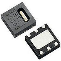
SHT21
Description
Humidity/Temperture Sensor
Manufacturer
SENSIRION
Datasheet
1.SHT21.pdf
(12 pages)
Specifications of SHT21
Operating Temperature Range
-40°C To +125°C
No. Of Pins
6
Supply Voltage
3V
Humidity Sensor Type
Capacitive
Sensor Case Style
DFN
Humidity Range
0% To 100%
Response Time
8s
Accuracy
± 2%
Supply Current
300µA
Available stocks
Company
Part Number
Manufacturer
Quantity
Price

Part Number:
SHT21
Manufacturer:
SENSIRION
Quantity:
20 000


Datasheet SHT21
Figure 12
abbreviations are explained in Table 5. SDA directions are seen
from the sensor. Bold SDA line is controlled by the sensor, plain
SDA line is controlled by the micro-controller. Note that SDA
valid read time is triggered by falling edge of anterior toggle.
Parameter
SCL frequency, f
SCL High Time, t
SCL Low Time, t
SDA Set-Up Time, t
SDA Hold Time, t
SDA Valid Time, t
SCL/SDA Fall Time, t
SCL/SDA Rise Time, t
Capacitive Load on Bus Line, C
Table 5 Timing specifications of digital input/output pads for I
fast mode. Entities are displayed in Figure 12. VDD = 2.1V to
3.6V, T = -40°C to 125°C, unless otherwise noted.
5 Communication with Sensor
SHT21 communicates with true I
information on I
Sections please refer to the following website:
http://www.standardics.nxp.com/support/i2c/.
Please note that all sensors are set to the same I
address, as defined in Section 5.3.
Furthermore, please note, that Sensirion provides an
exemplary sample code on its home page – compare
www.sensirion.com/sht21.
5.1
As a first step, the sensor is powered up to the chosen
supply voltage VDD (between 2.1V and 3.6V). After
power-up, the sensor needs at most 15ms, while SCL is
high, for reaching idle state, i.e. to be ready accepting
14
info@sensirion.com.
www.sensirion.com
DATA IN
DATA OUT
SCL
SDA
SDA
For sensors with alternative I
Start Up Sensor
t
SU
Timing Diagram for Digital Input/Output Pads,
SDA valid write
SCLL
SCL
SCLH
HD
2
VD
C beyond the information in the following
t
SCLH
SU
F
R
1/f
SCL
2
t
C address please contact Sensirion via
SCLL
t
HD
B
SDA valid read
t
VD
min
100
0.6
1.3
0
0
0
0
0
0
14
t
R
2
typ
C protocol. For
-
-
-
-
-
-
-
-
-
t
F
t
max Units
F
900
400
100
300
400
0.4
-
-
-
Version 1.1 – May 2010
t
MHz
R
µs
µs
pF
ns
ns
ns
ns
ns
70%
30%
30%
30%
70%
70%
2
2
C
C
commands from the master (MCU). Current consumption
during start up is 350µA maximum.
5.2
Each transmission sequence begins with Start condition
(S) and ends with Stop condition (P) as displayed in Figure
13 and Figure 14.
Figure 13 Transmission Start condition (S) - a high to low
transition on the SDA line while SCL is high. The Start condition
is a unique state on the bus created by the master, indicating to
the slaves the beginning of a transmission sequence (bus is
considered busy after a Start).
Figure 14 Transmission Stop condition (P) - a low to high
transition on the SDA line while SCL is high. The Stop condition
is a unique state on the bus created by the master, indicating to
the slaves the end of a transmission sequence (bus is
considered free after a Stop).
5.3
After sending the Start condition, the subsequent I
header consists of the 7-bit I
and an SDA direction bit (Read R: ‘1’, Write W: ‘0’). The
sensor indicates the proper reception of a byte by pulling
the SDA pin low (ACK bit) after the falling edge of the 8
SCL clock. After the issue of a measurement command
(‘1110’0011’ for temperature, ‘1110’0101’ for relative
humidity’), the MCU must wait for the measurement to
complete. The basic commands are summarized in Table
6. Hold master or no hold master modes are explained in
next Section.
Table 6 Basic command set, RH stands for relative humidity,
and T stands for temperature
Command
Trigger T measurement
Trigger RH measurement
Trigger T measurement
Trigger RH measurement
Write user register
Read user register
Soft reset
SCL
SDA
SCL
SDA
Start / Stop Sequence
Sending a Command
Comment
hold master
hold master
no hold master 1111’0011
no hold master 1111’0101
2
C device address ‘1000’000’
Code
1110’0011
1110’0101
1110’0110
1110’0111
1111’1110
7/12
30%
30%
70%
70%
30%
70%
70%
30%
2
C
th
Related parts for SHT21
Image
Part Number
Description
Manufacturer
Datasheet
Request
R


Part Number:
Description:
MODULE SENSOR TEMP+HUMIDITY
Manufacturer:
Parallax Inc
Datasheet:

Part Number:
Description:
Humidity Sensor Filter Cap
Manufacturer:
SENSIRION
Datasheet:

Part Number:
Description:
Sensor Evaluation Kit
Manufacturer:
SENSIRION
Datasheet:

Part Number:
Description:
Sensor Evaluation Kit
Manufacturer:
SENSIRION
Datasheet:
Part Number:
Description:
Sensor Evaluation Kit
Manufacturer:
SENSIRION
Datasheet:
Part Number:
Description:
Sensor Evaluation Kit
Manufacturer:
SENSIRION
Datasheet:


Part Number:
Description:
SENSOR, MASS FLOW
Manufacturer:
SENSIRION
Datasheet:

Part Number:
Description:
Humidity Sensor
Manufacturer:
SENSIRION
Datasheet: