FS1L.A.1L.195 IST, FS1L.A.1L.195 Datasheet - Page 3
FS1L.A.1L.195
Manufacturer Part Number
FS1L.A.1L.195
Description
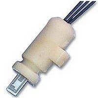
FLOW SENSOR, FLUIDS, MOULDED
Manufacturer
IST
Datasheet
1.FS1L.A.1L.195.pdf
(3 pages)
Specifications of FS1L.A.1L.195
Supply Voltage Range Dc
0V To 10V
Accuracy
± 3%
Flow Measuring Range
0.01m/s To 10m/s
Connection Size
6mm
Supply Voltage Dc Max
10V
External Diameter
6mm
External Length / Height
14mm
Lead
RoHS Compliant
Lead Length
176mm
Measuring Range
0.01
Rohs Compliant
Yes


As shown on the scheme to the right, the heater R
sensor R
essential to determine the correct values of the resistors R1,
R2, and R3. The bridge is in balance as soon as the desired
temperature difference between R
10K. At a changing flow the bridge voltage U_Bs needs to be
controlled in dependence of the bridge balance V1-V2. The
values for R1…R3 are depending on the temperature
difference dT and the medium which should be measured.
We will provide you with the values of R1…R3 , depending
on the application.
For calibration the R2 needs to be adjusted within a range of
The method of adjustment relies on the application.
Typical signal – curve between 0 .... 0.8 m/s
Option
The electric connection can be provided customer-specific.
If a connector is requested we provide e.g. the JST connector EHR-3 with 3 pins, polarized and
with a latch locking system.
Flow Sens FS1L / FS1LA
Thermal Mass Flow Sensor for
all-purpose use in Liquids
Electronic circuit recommendation
5%.
7.5
6.5
5.5
4.5
3.5
8
7
6
5
4
0
S
need to be connected in a bridge circuit. It is
0.1
0.2
0.3
Flow velocity [m/s]
S
and R
0.4
H
has reached e.g.
0.5
0.6
H
and
0.7
0.8
R2
R
V1
R1
V1
V2
S
Principle of the heating controller
+
-
GND
V
U_Bs
+
-
R3
V2
R
Sensor
H
U_Bs
Related parts for FS1L.A.1L.195
Image
Part Number
Description
Manufacturer
Datasheet
Request
R


Part Number:
Description:
FLOW SENSOR, GAS
Manufacturer:
IST
Datasheet:

Part Number:
Description:
FLOW SENSOR, GAS, MOULDED
Manufacturer:
IST
Datasheet:
Part Number:
Description:
SENSOR, FLOW, GAS
Manufacturer:
IST
Datasheet:
Part Number:
Description:
SENSOR, FLOW, GAS, MOLDED
Manufacturer:
IST
Datasheet:

Part Number:
Description:
Humidity Sensor
Manufacturer:
IST
Datasheet:

Part Number:
Description:
SENSOR, HUMIDITY, MODULE
Manufacturer:
IST
Datasheet:
Part Number:
Description:
SENSOR, HUMIDITY & TEMP, CAPACITIVE
Manufacturer:
IST
Datasheet:
Part Number:
Description:
Humidity Sensor
Manufacturer:
IST
Datasheet:
Part Number:
Description:
Humidity Sensor
Manufacturer:
IST
Datasheet:
Part Number:
Description:
Humidity Sensor
Manufacturer:
IST
Datasheet:

Part Number:
Description:
SENSOR, PT100, SMD0805, CLASS A
Manufacturer:
IST
Datasheet:

Part Number:
Description:
SOT223/1,5A LOW DROP RE 1.8V
Manufacturer:
Semtech Corporation

Part Number:
Description:
2.7V to 5.5V Single Supply CMOS Op Amp
Manufacturer:
Microchip Technology
Part Number:
Description:
2.7V to 5.5V Single Supply CMOS Op Amp
Manufacturer:
Microchip Technology