SMB55RA BANNER ENGINEERING, SMB55RA Datasheet - Page 8
SMB55RA
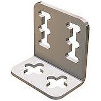
Manufacturer Part Number
SMB55RA
Description
Sensor Mounting Bracket
Manufacturer
BANNER ENGINEERING
Specifications of SMB55RA
For Use With
R58E Series Expert Register Mark Sensors
Lead Free Status / Rohs Status
RoHS Compliant part


8
R58 Expert
In addition to its configuration function, the remote input may be used to disable the push
buttons for security. Disabling the push buttons prevents unauthorized adjustment of the
configuration settings. Connect the gray wire of the sensor as described on page 3, and four-
pulse to either enable or disable the push buttons (0.04 sec. ≤ “T” ≤ 0.8 sec.):
NOTE: Push buttons can be disabled/enabled from the remote line only.
The R58E includes a total of eight size M5 threaded holes used for mounting (see dimension
drawing on page 11). These threaded holes are positioned to match the mounting hole
patterns common to other registration mark sensors. The R58E includes four M5 x 0.8 x 6 mm
stainless steel cap screws and a hex key wrench.
The R58E focus is 10 mm (0.39") from the lens surface. The R58E must be mounted within 3
mm (0.12") of this distance from the surface of the material for reliable sensing
(Figure 6). Consider the following when mounting the R58E:
• W henever possible, it is a good idea to sense a web material at a location where it passes
• W hen sensing a registration mark on a reflective (shiny) material, mount the R58E at
• C lear materials are poor reflectors of light. When sensing a mark printed on a clear material
Lens Location
The lens may be installed at either of two lens ports (see Figure 6). The lens and the lens port
cap are both threaded and may be exchanged by hand; no tools are required. The lens and
cap both include an o-ring seal.
NOTE: T he lens port cap must be installed on the unused port for reliable operation. Fully seat
over a tension bar or roller, to minimize the adverse effects of web “flutter” or sag (Figure 7).
an angle which places the lens centerline at approximately 15° off perpendicular to the
material’s surface (Figure 8). This “skew angle” will minimize strong direct reflections (which
tend to overwhelm the sensor), and allow the sensor to discern the relatively small optical
contrast offered by differences in colors.
(e.g., a clear poly web), position a reflective surface directly behind the clear material to
return light to the R58E. The printed mark, regardless of its color, then becomes the dark
condition, as it blocks the light from reaching the reflective surface. Most clear materials are
also shiny; it is important to include a 15° skew angle when sensing clear materials (Figure
8).
P/N 122928 rev. C
T
the lens cap to ensure a liquid-tight seal.
T
> 2 seconds
Push Button Enable/Disable (Lockout)
™
T
Registration Mark Sensors
T T T
Installation Notes
T
T
T
T
T
T
T
T
T
T
T
T
T
T
T
T
T
T
T
T
T
T
T
T
T
T
T
T
T
T
T
T
T
T
0.8 seconds
T
T
T
T
T
T
T
T
T
T
T
T
Banner Engineering Corp. • Minneapolis, MN U.S.A
www.bannerengineering.com • Tel: 763.544.3164
Figure 6. R58E lens positions
Figure 7. Mounting for sensing opaque non-
Figure 8. Mounting for sensing opaque
Opaque Reflective
Transparent or
Web Material
Tension Bar
Mount the R58E at approximately 15 ° from perpendicular to
Tension Bar
Approximately 15 º
Roller or
Roller or
90º
Mount the R58E Perpendicular to
reflective materials
reflective and transparent materials
non-reflective (matte) materials
transparent and opaque reflective materials
Surface of
Material
Lens
Cap
10 3 mm
Focus Distance
10.0 mm (0.39")
R58E
Opaque,
Non-reflective
Web Material
10 3 mm
Focus Distance
10.0 mm (0.39")
R58E
Cap
Lens
Related parts for SMB55RA
Image
Part Number
Description
Manufacturer
Datasheet
Request
R

Part Number:
Description:
Photoelectric Sensor
Manufacturer:
BANNER ENGINEERING
Datasheet:

Part Number:
Description:
Photoelectric Sensor
Manufacturer:
BANNER ENGINEERING
Datasheet:

Part Number:
Description:
LEDIR70XD4-XM-81039 MAX INTENS STROBE ONLY NO BANNER MARKS
Manufacturer:
BANNER ENGINEERING
Part Number:
Description:
M18SP6DL-72225 LABELED MOELLER NO BANNER MARKINGS BULK PACK
Manufacturer:
BANNER ENGINEERING
Part Number:
Description:
M18SP6DLQ-72226 LABLED MOELLER NO BANNER MARKINGS BULK PACK
Manufacturer:
BANNER ENGINEERING
Part Number:
Description:
M18SP6L-72223 LABELED MOELLER NO BANNER MARKINGS BULK PACK
Manufacturer:
BANNER ENGINEERING
Part Number:
Description:
M18SP6LQ-72224 LABELED MOELLER NO BANNER MARKINGS BULK PACK
Manufacturer:
BANNER ENGINEERING
Part Number:
Description:
P4D1-77908 P4 DRIVER GENERIC NO BANNER MARKINGS RESALE TO CUSTOMER
Manufacturer:
BANNER ENGINEERING
Part Number:
Description:
Photoelectric Sensor
Manufacturer:
BANNER ENGINEERING
Datasheet:

Part Number:
Description:
Programmable Indicator Light
Manufacturer:
BANNER ENGINEERING
Datasheet:
Part Number:
Description:
INDICATOR LED PANEL 50MM GRN/RED/YEL 30V
Manufacturer:
BANNER ENGINEERING
Datasheet:
Part Number:
Description:
Programmable Indicator Light
Manufacturer:
BANNER ENGINEERING
Datasheet: