KET 13 EUCHNER, KET 13 Datasheet - Page 16
KET 13
Manufacturer Part Number
KET 13
Description
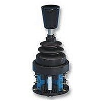
JOYSTICK SWITCH
Manufacturer
EUCHNER
Datasheet
1.KES_13.pdf
(27 pages)
Specifications of KET 13
Contact Configuration
SPST-CO
Contact Voltage Ac Max
230V
Contact Voltage Dc Max
24V
Contact Current Ac Max
4A
Contact Current Dc Max
2A
Switch Terminals
Solder
Handle Style
Lever


Joystick switches
Series KC...
Dimension drawing
16
Main actuating directions
control panel installation at rear or with front plate
1 to 8 actuating directions with 1 or 2 switching positions for each actuating direction
Switching positions as stayput or spring return operation in various combinations
Centre position switch
Pushbutton in handle
1, 2, 3 and 4
Subject to technical modifications; no responsibility is accepted for the accuracy of this information.
Diagonal actuating directions
Centre position switch Z
(actuated in centre position)
Switching position II
5, 6, 7 and 8
Switching position I
(4 + 1)
(3 + 4)
(contacts)
Germanischer Lloyd
Certificate no. 17 041 - 00 HH
1) Panel cutout for assembly
with bellows W
4
Top view of actuating lever
8
7
Actuating directions
II
II
II
I
I
I
1 2 3
3
3
1
0
2
II
II
I
I
1
1)
I
I
I
∅
86 / 4 x
II
II
II
5
6
∅
(with protective cap)
2
(1 + 2)
(Diagonal
actuating directions)
Switching positions
(2 + 3)
5,5
Bellows W
for panel mounting
Pushbutton D
Interlock V
for surface
Bellows X
mounting
Related parts for KET 13
Image
Part Number
Description
Manufacturer
Datasheet
Request
R

Part Number:
Description:
JOYSTICK SWITCH
Manufacturer:
EUCHNER
Datasheet:

Part Number:
Description:
ACTUATOR
Manufacturer:
EUCHNER
Datasheet:

Part Number:
Description:
ACTUATOR
Manufacturer:
EUCHNER
Datasheet:

Part Number:
Description:
ACTUATOR
Manufacturer:
EUCHNER
Datasheet:

Part Number:
Description:
ACTUATOR
Manufacturer:
EUCHNER
Datasheet:

Part Number:
Description:
JOYSTICK SWITCH
Manufacturer:
EUCHNER
Datasheet:

Part Number:
Description:
JOYSTICK SWITCH
Manufacturer:
EUCHNER
Datasheet:

Part Number:
Description:
JOYSTICK SWITCH
Manufacturer:
EUCHNER
Datasheet:


Part Number:
Description:
LIMIT SWITCH, SINGLE
Manufacturer:
EUCHNER
Datasheet:

Part Number:
Description:
SAFETY SWITCH
Manufacturer:
EUCHNER
Datasheet:

Part Number:
Description:
SAFETY SWITCH
Manufacturer:
EUCHNER
Datasheet:

Part Number:
Description:
SAFETY SWITCH
Manufacturer:
EUCHNER
Datasheet:

Part Number:
Description:
SAFETY SWITCH
Manufacturer:
EUCHNER
Datasheet:

Part Number:
Description:
SAFETY SWITCH
Manufacturer:
EUCHNER
Datasheet: