HW4K-2AF20 IDEC, HW4K-2AF20 Datasheet - Page 56
HW4K-2AF20
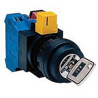
Manufacturer Part Number
HW4K-2AF20
Description
SWITCH, KEY OPERATED, 2NO, 10A, 600V
Manufacturer
IDEC
Datasheet
1.HW1B-M0.pdf
(56 pages)
Specifications of HW4K-2AF20
Contact Configuration
DPST-NO
Switch Operation
ON-(ON)
Actuator Style
Flat
No. Of Switch Positions
2
Contact Voltage Ac Nom
600V
Contact Voltage Dc Nom
220V
Contact Current Max
10A
Lead Free Status / RoHS Status
Lead free / RoHS Compliant


Replacement of Lamps
Lamps can be replaced by using the lamp holder tool (OR-55) from the front of
the panel, or by removing the contact block assembly from the operator unit.
Removing the Lamps from the Front of the Panel
Removal
1. To remove, slip the lamp holder
Installation
1. To install, insert the lamp head into the lamp holder tool, and hold the lamp
2. Place the pins on the lamp base to
About Pushbutton Switches
Narrow Mounting
use optional barriers to prevent interconnection between adjoining
terminals. The barriers can be attached simply by pressing them onto
the sides of contact blocks.
www.idec.com
illuminated units closely in a hori-
zontal row on 30-mm centers,
insert solid wires or stranded
wires into inside of the terminal
screw on the transformer (see
figure on the right) to prevent
short circuit between adjoining
terminals.
When mounting the units closely in a horizontal row on 30mm centers,
When mounting transformer type
removed or replaced!
using a flat screwdriver or
pincers, otherwise the push-
buttons may be damaged.
tool onto the lamp head lightly.
Then push slightly, and turn the
lamp holder tool counterclock-
wise.
as shown in the figure below.
the grooves in the lamp socket.
Insert the lamp and turn it clock-
wise.
The pushbuttons cannot be
Do not attempt to remove
Lamp
Oiltight Switches & Pilot Devices
Lamp Holder Tool
Pushbuttons
X1
USA: (800) 262-IDEC or (408) 747-0550, Canada: (888) 317-IDEC
Inside Inside
X2
30
Barrier
Dual Pushbuttons Instructions con’t
X1
Lamp Base
30
Do not attempt
to remove the
pushbuttons!
X2
Tightening Torque for Terminal Screws
Installation of LED Illuminated Units
against electrical noise, if necessary.
Applicable Wiring
mum) One or two wires can be connected.
crimping terminal to prevent electrical shocks.
Installing the Rubber Cover
are subjected to water splash or an excessive amount of dust, make
sure to use the HW9Z-D7D rubber boot (IP65) which is ordered sepa-
rately.
the operator. Pull out the seals of the rubber boot and place them
around the operator sleeve as shown. Make sure that the seals are not
twisted or tucked inside and that the gasket does not remain, other-
wise the normal waterproof and dustproof characteristics are not
ensured.
Tighten the M3.5 terminal screws to a torque of 1.0 to 1.3
When using full voltage type LED illuminated units, provide protection
The applicable wire size is 2 mm
Applicable Crimping Terminal
Be sure to use an insulation tube or cover on the crimping part of the
Solid Wire
Note: When connecting wires to contact blocks or transformers in
When using the HW7D pushbuttons in places where the pushbuttons
Notes for Installing the Rubber Cover
Remove the gasket from the operator, and install the rubber boot on
Remove the gasket.
the direction shown below, keep the insulation stripping length
6.6 mm at the maximum.
Gasket
Remove
4 max.
Install the rubber boot
on the pushbuttons.
Seals
Seals
2
maximum. (solid wire ø1.6 mm maxi-
ø3.6 min.
8 max.
Install
5.5 min.
X1
ø22mm - HW Series
X2
Rubber boot is
installed.
N·m
.
A3-107
A3
Related parts for HW4K-2AF20
Image
Part Number
Description
Manufacturer
Datasheet
Request
R

Part Number:
Description:
SWITCH, KEY OPERATED, 1NO/1NC, 10A, 600V
Manufacturer:
IDEC
Datasheet:

Part Number:
Description:
HW4K-2B HW Mtl Bzl Oper Slctr 2pos Key-RR Maint
Manufacturer:
IDEC
Part Number:
Description:
HW4K-31BF20 HW Mtl Bzl KS 3pos Sprg-Rt Key-RR 2NO
Manufacturer:
IDEC
Datasheet:
Part Number:
Description:
SWITCH, KEY OPERATED, 2NO, 10A, 600V
Manufacturer:
IDEC
Datasheet:
Part Number:
Description:
PUSHBUTTONS: HW SERIES ASSEMBLED PRODUCTS
Manufacturer:
IDEC
Datasheet:
Part Number:
Description:
Key Selector Switch 22mm Maintained 3-Position 1NO-1NC
Manufacturer:
IDEC
Datasheet:
Part Number:
Description:
SWITCH, KEY OPERATED, DPST-NC, 10A, 600V
Manufacturer:
IDEC
Datasheet:
Part Number:
Description:
Cable; Between IDEC MicroSmart (port 1 or 2) and HG2F/3F/4F; 5 ft.
Manufacturer:
IDEC Corporation
Datasheet:
Part Number:
Description:
Cable; Between IDEC Micro^3C/ONC/MicroSmart (port 2) PLCs and HG2F/3F/4F; 5 ft.
Manufacturer:
IDEC Corporation
Datasheet:
Part Number:
Description:
Angled Key for Idec HS6B Safety Switch
Manufacturer:
IDEC Corporation
Datasheet:
Part Number:
Description:
INDICATOR INCANDESCENT LAMP, GREEN
Manufacturer:
IDEC
Datasheet:

Part Number:
Description:
LAMP, INDICATOR, INCAND, AMB
Manufacturer:
IDEC
Datasheet:
Part Number:
Description:
LAMP, INDICATOR, INCAND, GRN
Manufacturer:
IDEC
Datasheet:
Part Number:
Description:
LAMP, INDICATOR, INCAND, GRN
Manufacturer:
IDEC
Datasheet:
Part Number:
Description:
LAMP, INDICATOR, INCANDESCENT, RED
Manufacturer:
IDEC
Datasheet: