HW4K-2AF20 IDEC, HW4K-2AF20 Datasheet - Page 55
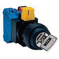
HW4K-2AF20
Manufacturer Part Number
HW4K-2AF20
Description
SWITCH, KEY OPERATED, 2NO, 10A, 600V
Manufacturer
IDEC
Datasheet
1.HW1B-M0.pdf
(56 pages)
Specifications of HW4K-2AF20
Contact Configuration
DPST-NO
Switch Operation
ON-(ON)
Actuator Style
Flat
No. Of Switch Positions
2
Contact Voltage Ac Nom
600V
Contact Voltage Dc Nom
220V
Contact Current Max
10A
Lead Free Status / RoHS Status
Lead free / RoHS Compliant


A3
ø22mm - HW Series
HW Series Safety Precautions
A3-106
• Turn off power to HW series control units before starting installa-
• To avoid the possibility of burning yourself, use the lamp holder tool
Panel Mounting
Remove the contact block assembly from the operator (for trans-
former type pilot lights, remove the transformer from the illumination
unit). Remove the locking ring from the operator. Insert the operator
into the panel cut-out from the front, tighten the locking ring from the
back, then install the contact block assembly to the operator.
Removing and Installing the Contact Block Assembly
1. To remove the operator from the contact block, turn the locking
2. To reinstall, place the TOP markings on the operator and the con-
Notes for Panel Mounting
1. When mounting the operator onto a panel, use the optional locking
2. For the contact blocks and transformers housing LED and incan-
Replacement of Lens
Removing
• Remove the lens by inserting a screwdriver into the recess of the
Installing
• Install the lens in the recess between the buttons by pressing
tion, removal, wiring, maintenance, and inspection of the products.
Failure to turn power off may cause electrical shocks or fire haz-
ard.
when replacing lamps.
lever in the direction of the arrow shown below. The operator can
now be removed.
tact block mounting adapter in the same direction, and insert the
operator into the contact block mounting adapter. Then turn the
locking lever in the opposite direction.
ring wrench (MW9Z-T1) to tighten the locking ring. Tightening
torque must not exceed 2.0 N·m. Do not use pliers. Excessive tight-
ening will damage the locking ring.
descent lamps, make sure not to press the lamps too hard, other-
wise the lamp socket may be damaged.
lens through the bezel.
against the bezel.
www.idec.com
Oiltight Switches & Pilot Devices
Dual Pushbutton Instructions
HW General Instructions
HW Safety Precautions
USA: (800) 262-IDEC or (408) 747-0550, Canada: (888) 317-IDEC
For wiring, use wires of a proper size to meet voltage and current
requirements. Tighten the M3.5 terminal screws to a tightening
torque of 1.0 to 1.3
overheating and fire.
Safety Lever Lock
IDEC strongly recommends using the safety lever lock (HW9Z-LS, yellow) to
prevent heavy vibration or maintenance personnel from unlocking the con-
tact assembly.
1. HW series can be mounted vertically with a minimum spacing of 55
2. Mount the control unit onto the panel, lock the lever, and push in
3. When the spacing is narrower than the recommended value, with
4. To remove the safety lever lock, insert a flat screwdriver into the
mm but spacing should be determined to ensure easy operation
(recommended minimum spacing: 100 mm).
the safety lever lock to install.
the lever unlocked, mount the safety lever lock and insert the con-
tact unit to the operator. Then, lock the lever and strongly push in
the safety lever lock to install.
safety lever and push upwards.
Contact Block
Removing and Installing the Safety Lever Lock
Safety Lever Lock
Screwdriver
Removing
N·m
. Failure to tighten terminal screws may cause
Panel
Remove
Operator
Safety Lever Lock
Lock Lever
Installing
Install
Push
Lock
Related parts for HW4K-2AF20
Image
Part Number
Description
Manufacturer
Datasheet
Request
R

Part Number:
Description:
SWITCH, KEY OPERATED, 1NO/1NC, 10A, 600V
Manufacturer:
IDEC
Datasheet:

Part Number:
Description:
HW4K-2B HW Mtl Bzl Oper Slctr 2pos Key-RR Maint
Manufacturer:
IDEC
Part Number:
Description:
HW4K-31BF20 HW Mtl Bzl KS 3pos Sprg-Rt Key-RR 2NO
Manufacturer:
IDEC
Datasheet:
Part Number:
Description:
SWITCH, KEY OPERATED, 2NO, 10A, 600V
Manufacturer:
IDEC
Datasheet:
Part Number:
Description:
PUSHBUTTONS: HW SERIES ASSEMBLED PRODUCTS
Manufacturer:
IDEC
Datasheet:
Part Number:
Description:
Key Selector Switch 22mm Maintained 3-Position 1NO-1NC
Manufacturer:
IDEC
Datasheet:
Part Number:
Description:
SWITCH, KEY OPERATED, DPST-NC, 10A, 600V
Manufacturer:
IDEC
Datasheet:
Part Number:
Description:
Cable; Between IDEC MicroSmart (port 1 or 2) and HG2F/3F/4F; 5 ft.
Manufacturer:
IDEC Corporation
Datasheet:
Part Number:
Description:
Cable; Between IDEC Micro^3C/ONC/MicroSmart (port 2) PLCs and HG2F/3F/4F; 5 ft.
Manufacturer:
IDEC Corporation
Datasheet:
Part Number:
Description:
Angled Key for Idec HS6B Safety Switch
Manufacturer:
IDEC Corporation
Datasheet:
Part Number:
Description:
INDICATOR INCANDESCENT LAMP, GREEN
Manufacturer:
IDEC
Datasheet:

Part Number:
Description:
LAMP, INDICATOR, INCAND, AMB
Manufacturer:
IDEC
Datasheet:
Part Number:
Description:
LAMP, INDICATOR, INCAND, GRN
Manufacturer:
IDEC
Datasheet:
Part Number:
Description:
LAMP, INDICATOR, INCAND, GRN
Manufacturer:
IDEC
Datasheet:
Part Number:
Description:
LAMP, INDICATOR, INCANDESCENT, RED
Manufacturer:
IDEC
Datasheet: