7846K1 EATON, 7846K1 Datasheet - Page 28
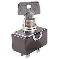
7846K1
Manufacturer Part Number
7846K1
Description
SWITCH, KEY LOCK, DPST, 20A, 240V
Manufacturer
EATON
Datasheet
1.8980P28.pdf
(29 pages)
Specifications of 7846K1
Contact Configuration
DPST
Switch Operation
OFF-ON-OFF-ON
No. Of Switch Positions
1
Contact Voltage Ac Nom
240V
Contact Current Max
20A
Switch Terminals
Quick Connect
Circuitry
DPST
Lead Free Status / RoHS Status
Lead free / RoHS Compliant


“THREE INDEPENDENT” ON-ON-ON CIRCUIT DIAGRAM
Note: For switch modified with “Three Independent” ON-ON-ON Special
Circuit. External Jumpers are required. Converts 2PDT to 1P3T or 4PDT to
2P3T. User to connect wiring per instructions given below.
4.28
TERMINAL MARKINGS
Independent
Connect Circuit “B” to Terminals
Connect Circuit “C” to Terminals
Connect Circuit “A” to Terminals
Connect Common to Terminals
Double Pole
Single Pole
Four Pole
3 “ON”
1P3T
Connection Points
1
2
3
1
2
3
1
2
3
4
5
6
4
5
6
Poles
7
8
9
No.
of
1
10
11
12
4
1
4
Circuit A
Position
UP
2
5
SPECIAL DEVICES AND ACCESSORIES
Rocker, Toggle and Pushbutton Switch Circuit Diagrams
TERMINAL IDENTIFICATION
When specified on order, switches
will have the terminals identified as
shown in the illustration at right.
Terminal markings will be
ink-stamped on the side of the
switch case and unused terminal
positions will not be identified.
All views are rear of switch with
keyway or flat down as applicable.
Terminal numbers 2, 2 & 5, and
5 & 8 are considered inboard
terminals for single, two and four
pole switches respectively. All
others are considered outboard.
3
6
Circuit with Lever in
CENTER Position
(Maintained)
1
4
Circuit B
2
5
Single Pole
3
6
2
6
4
1
DOWN Position
(Keyway)
1
4
Circuit C
2
5
3
6
LEGENDS
See page 4.29
See pages 1.41-1.45
ROCKER, TOGGLE AND PUSHBUTTON CIRCUIT DIAGRAMS
Q Poles 11 and 12 may be eliminated for 3 pole devices.
W Poles 10, 11 and 12 may be eliminated for 3 pole devices.
E Dependent Lamp.
R Independent Lamp.
T Two Circuit — Indicates a special type of double throw switch in which the two circuits being controlled
Y For 206 Series, an additional lamp is available.
U Available in 1PDT or 2PDT.
may be independent of each other.
(4 P . S.T.)
(4 P . D.T.)
(1 P . D.T.)
(2 P . D.T.)
(1 P . D.T.)
(1 P . S.T.)
(2 P . S.T.)
(1 P . S.T.)
Circuit
Letter
ROCKER, TOGGLE AND PUSHBUTTON SWITCH LEGEND
G
H
A
B
C
D
E
F
E
R
Q
W
for 92, Midsize and Elite Circuit Diagrams.
Contact Terminal — will make contact with switch lever
Isolated Terminal — does not make contact with lever
Center terminal and switch lever
Bulb
Momentary Contact
Denotes mechanical contact portion
for NGR Circuit Diagrams.
Schematic
2
3
1
2
3
3
3
2
1
2
3
3
5
6
4
5
6
2
2
2
3
1
2
3
8
9
7
8
9
4
6
5
6
4
5
6
6
4
10
12
11
11
12
(2 Circuit)
(2 Circuit)
(1 P . D.T.)
(2 P . D.T.)
(1 P . D.T.)
(1 P . S.T.)
(2 P . S.T.)
(2 P . S.T.)
Circuit
Letter
N
Q
M
K
P
J
L
I
Y
U
T
B
A
Schematic
C
C
2 4
1 3
1
2
1
3
4
4
6
3
NC
NC
NO
H
G
NO
Related parts for 7846K1
Image
Part Number
Description
Manufacturer
Datasheet
Request
R

Part Number:
Description:
EATON C D EATON RPLT BATT UPS12-300MR 12V 75AH
Manufacturer:
EATON

Part Number:
Description:
PROGRAMMABLE LOGIC CONTROLLER
Manufacturer:
EATON CUTLER HAMMER
Part Number:
Description:
EATON ELECTRICAL - LG 4 P PLUG IN BLOCK UL/IEC
Manufacturer:
EATON CUTLER HAMMER
Part Number:
Description:
Eaton BladeUPS 3U EBM
Manufacturer:
EATON POWERWARE/MGE OFFICE PROTECTION
Part Number:
Description:
Industrial Network Management Card Modbus & Jbus - Powerware And Eaton Series
Manufacturer:
EATON POWERWARE/MGE OFFICE PROTECTION
Part Number:
Description:
Eaton 9130 1 KVA MARINE
Manufacturer:
EATON POWERWARE/MGE OFFICE PROTECTION
Part Number:
Description:
Handle Tie Bar For (2) - 1 Pole Type BR Breakers
Manufacturer:
EATON CUTLER HAMMER
Part Number:
Description:
Type CL Breaker 25A/1Pole 120/240V 10K-Classified 1" Ckt Bkr
Manufacturer:
EATON CUTLER HAMMER