7846K1 EATON, 7846K1 Datasheet
7846K1
Specifications of 7846K1


Related parts for 7846K1


7846K1 Summary of contents
Page 1
... Eaton ® Commercial Controls Division S Series Snap Switches . . . . . . . . . . . . . . . . . . . . . . . . . . . 4.2 Snap Switch Pushbutton Superstructure . . . . . . . . . . . . . . 4.8 Door Interlock Switches . . . . . . . . . . . . . . . . . . . . . . . . . . . 4.9 Wiper/Dimmer Controls . . . . . . . . . . . . . . . . . . . . . . . . . . 4.10 Rotary Wiper Controls . . . . . . . . . . . . . . . . . . . . . . . . . . . 4.12 Keylock Switches . . . . . . . . . . . . . . . . . . . . . . . . . . . . . . . 4.14 ON-OFF Trigger Switch . . . . . . . . . . . . . . . . . . . . . . . . . . . 4.16 AC Variable Speed Control Switch . . . . . . . . . . . . . . . . . . 4.17 Industrial Rocker . . . . . . . . . . . . . . . . . . . . . . . . . . . . . . . 4.18 Locking Rocker 4.18 Sump Pump Switches ...
Page 2
... SPECIAL DEVICES AND ACCESSORIES S Series Snap Action Switches DESCRIPTION The S Series product group expands Eaton’s snap action switch portfolio to cover all major amperages and operating forces. A wide range of sizes and options gives customers the ability to select the most appropriate switch for their specifi ...
Page 3
HOW TO ORDER — SNAP ACTION SWITCH To determine your Complete Catalog Number, you must start with the appropriate Base Circuit Number and add the appropriate Code Letters and/or Numbers as in the example below: Start with this Base Circuit ...
Page 4
... SPECIAL DEVICES AND ACCESSORIES S Series Snap Action Switches OPERATING FORCE REFERENCE TABLE KEY Abbreviation Description Abbreviation OF Operating Force PT OP Operating Position OT OPERATING FORCE REFERENCE TABLE Lever OF OF Maximum Type Code g/ounce mm (inches SERIES — ULTRAMINIATURE C 90/3.25 A 7.00 ± .30 (.276) E 150/5.25 C 30/1.05 C 8.40 ± ...
Page 5
OPERATING FORCE REFERENCE TABLE (continued) Lever OF Maximum Type Q Code Code SERIES — GENERAL A 18/.63 45/1.58 75/2.63 18/.63 45/1.58 75/2.63 B 8/.28 27/.95 37/1.30 8/.28 22/.77 37/1.3 C 5/.175 16/.56 22/.77 ...
Page 6
... SPECIAL DEVICES AND ACCESSORIES S Series Snap Action Switches LEVER TYPE REFERENCE TABLE These drawings show the SG and SJ Series. Construction for other Series may vary slightly. Refer to Selection Table (page 4.3) for Lever Length. MECHANICAL TERMS Free Position The unoperated, fully extended position of the actuator. ...
Page 7
DIMENSIONS APPROXIMATE IN MM (INCHES) SC SERIES — ULTRAMINIATURE 12.70 (.500) 5.20 0.10 (.200) ø2.20 ø2.05 HOLE 0.90 (.090) (.080) (.035) 6.50 3.15 (.260) (.120) 5.80 (.200) 5.80 (.200) 12.80 0.15 (.500) SE SERIES — SUBMINIATURE 14.50 (.570) 3.00 0.10 ...
Page 8
SPECIAL DEVICES AND ACCESSORIES Snap Switch Pushbutton Superstructure DESCRIPTION These Non-Illuminated Pushbutton Actuators complement our S Series Snap Switch Line featured on pages are available in three different non-illuminated versions. The line is complete with attractive colored pushbutton caps ...
Page 9
... Materials and Finishes: When the door is open, the Switch — Contact Eaton actuator springs out thereby Customer Service. opening the power circuit. 1-800-962-0820 DOOR INTERLOCK SELECTION TABLE ...
Page 10
... DIMMER AND WIPER CONTROLS Paddle and Slide Controls DESCRIPTION Eaton’s unique family of dimmer and wiper controls are field proven to be the market’s most dependable controls. Although originally designed for the heavy truck market, applications in various other types of vehicles exist. Paddle and slide versions ...
Page 11
DIMENSIONS APPROXIMATE IN MM (INCHES) PADDLE CONTROL 49.78 (1.960) 26.01 (1.024 33.83 40.18 (1.332) (1.582) White Yellow DIMENSIONS APPROXIMATE IN MM (INCHES) SLIDE CONTROL R 3.96 Typ (R .156) 17.15 26.01 (.675) (1.024) 11.38 R 2.03 Typ (.448) ...
Page 12
DIMMER AND WIPER CONTROLS RW 200 Series Rotary Wiper DESCRIPTION The Rotary Wiper has been designed highly durable rotary wiper control for the transportation industry. The RW200 series wiper has four wiper control positions via a ...
Page 13
DIMENSIONS APPROXIMATE IN MM (INCHES) RW200 SERIES Slowest Intermittent Off/Park Speed 20º 70º Fastest Intermittent Speed Washer (Push In) Continuous 20º Low Speed 20º Ref Continuous Fast Speed +.25 15.47 -. +.010 .609 -.015 2.51 (.099) Yellow Lead ...
Page 14
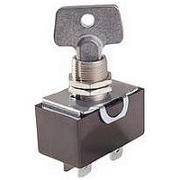
... CENTER AND RIGHT 8928K493 CENTER AND RIGHT 8928K494 CENTER 8283K150 CENTER 8370K150 CENTER 8370K151 LEFT 8370K152 CENTER AND RIGHT 8928K495 CENTER 8373K150 CENTER AND RIGHT 8373K151 Type of Catalog Key Style Q Termination Number Screw 7842K2 W A Screw 7842K3 W A Quick-Connect 7846K1 W E ...
Page 15
... Keyway 2. 1.12 - 1.17 D. (.080) (.085) (.044) (.046) 15/ T.P .T. 12.70 (.500) 18.24 (.718) 8.71 (.343) 33.32 (1.312) 23.01 (.906) 8928K493 General Purpose Keylock ...
Page 16
... Industrial The rugged PT Series Trigger Switch is designed for use in high performance, professionally rated power tools. UTILITY AND INDUSTRIAL ON-OFF TRIGGER SWITCHES SELECTION TABLE Ratings Poles and Throw Mounting UTILITY S.T. Nest 10A, 125V ...
Page 17
... P . S.T. A Plug- S.T. A Plug-in 7A, 125V S.T. B Screw Plug-in 6A, 250V S.T. B Screw Plug-in Q 8622K2: 4A, 125V. Series 8600 have higher ratings available. Contact your local Eaton Sales Representative. DIMENSIONS APPROXIMATE IN MM (INCHES) WIRING DIAGRAMS Line 1 Load 1 Diagram A Line 2 Load 2 Main Electronics Contact 1 1 Diagram B ...
Page 18
SPECIAL DEVICES AND ACCESSORIES Industrial Rocker Switch and Locking Rocker DESCRIPTION Locking Rocker This unique switch features a patented internal locking mechanism, which allows the switch to be locked in the off-position to prevent unauthorized or accidental operation. The ...
Page 19
... TO LOCK” across the top of the key in raised letters. Dielectric: Locking Rocker 1000V RMS minimum. Approvals: UL Recognized. CSA Certified. Contact your local Eaton Sales Representative for Selection Information and Optional Features. 52.58 (2.070) Max. 45.97 (1.810) Ref. 14.22 (.560) 3.05 (.120) Dia. ...
Page 20
... SPECIAL DEVICES AND ACCESSORIES Sump Pump Switches — AC Rated These completely molded, ruggedly constructed switch assemblies are designed specifically for sump pump and liquid level applications. All series feature Quick-make/Quick-break mechanisms with snap acting butt contacts. They provide high reliability and long life at an economical cost ...
Page 21
DIMENSIONS APPROXIMATE IN MM (INCHES) PEDESTAL TYPE WEIGHT/FLOAT SWITCH 7.92 (.312) Dia. 20.57 43˚ (.810) 5.16 Ref. 4.78 (.188) Dia. (.203) 2 Holes 33.02 (1.300) 33.02 (1.300) 11.10 (.437) 69.85 (2.750) 4.75 (.187) 91.44 (3.060) 31.75 (1.250) 20.57 (.810) WEIGHT/FLOAT ...
Page 22
... Flat Washer For 9.98 (.393 ) Bushing Plain Washer For 15/32 Bushing Internal Tooth Lockwasher Locking Ring Q Hardware items are sold for use with Eaton switches only. Minimum ordering quantity on all items is 100. DIMENSIONS APPROXIMATE IN MM (INCHES) HEXAGON LOCKNUTS KNURLED FACENUT OR FACENUTS ...
Page 23
... Snap-On Pushbutton Caps — Standard DESCRIPTION SELECTION TABLE These snap-on pushbutton Description caps are made of molded Black Molded plastic for use with grooved Red Molded style switches. They are ordered separately for user assembly. CAT. NO. 35-3338 Switch Catalog Locking Terminal Locknut ...
Page 24
... Color Black Knurled Facenuts Brite Clear Brite Black Beveled Facenuts Brite Clear Q Decorator Facenuts for designer line and 15/32 bushing switches, 15/32-32 thread. 4.24 Mounting Hardware and Keys: 1 hexagon locknut (Cat. No. 15-2528-2) and 1 bright chrome plated dress nut (Cat. No. 15-2528-2). Furnished unassembled ...
Page 25
... Binding Head 11-1766 #8-32 x 3/8 Binding Head 11-6074-4 #6-32 x 7/32 Binding Head 11-6085-2 Q Hardware items are sold for use with Eaton Switches only. Indicating Plates SELECTION TABLE Q Marking Keyway Location Opposite Keyway Keyway Side ON OFF ...
Page 26
SPECIAL DEVICES AND ACCESSORIES Accessories for EURO/SR, FULL SIZE, ESPORT and NGR Rockers DIMENSIONS APPROXIMATE IN MM (INCHES) Dimension applies at 43.10 .51 base of snap leg (1.697) 23.11 .51 ( .910 ) 35.36 .38 ( 1.392 ) NGR ...
Page 27
... C (.335) (.340) 13.46 13.97 D (.530) (.550) R 6. .250) (R .156) Part will also fit Eaton gang mounting boxes. Catalog Number Panel plug Catalog Number 53-3318 17-19263 and 17-19264. For use with EURO/SR R 3.18 22.02 (R .125) (.867) 44.02 (1.734) End 50.80 Bezel (2 ...
Page 28
... SPECIAL DEVICES AND ACCESSORIES Rocker, Toggle and Pushbutton Switch Circuit Diagrams TERMINAL IDENTIFICATION TERMINAL MARKINGS When specified on order, switches will have the terminals identifi shown in the illustration at right. Single Pole 2 Terminal markings will be 3 ink-stamped on the side of the switch case and unused terminal ...
Page 29
Rocker Switch Circuit Diagrams 92, MIDSIZE AND ELITE SERIES CIRCUIT DIAGRAMS Circuit with Rocker in Circuit Number Schematic UP (Circuit Position Designation) NON-ILLUMINATED S.T S.T ...