KMZ10C,112 NXP Semiconductors, KMZ10C,112 Datasheet - Page 24
KMZ10C,112
Manufacturer Part Number
KMZ10C,112
Description
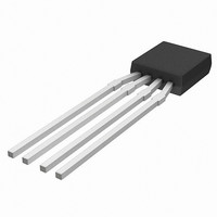
IC MAGNETIC FIELD SENSOR SOT195
Manufacturer
NXP Semiconductors
Type
Special Purposer
Specifications of KMZ10C,112
Sensing Range
2mV/V
Voltage - Supply
5 V ~ 10 V
Output Type
Analog
Operating Temperature
-40°C ~ 150°C
Package / Case
SOT-195
Mounting Style
SMD/SMT
Maximum Operating Temperature
+ 150 C
Minimum Operating Temperature
- 40 C
Supply Voltage (min)
5 V
Supply Voltage (max)
10 V
Operating Temperature (min)
-40C
Operating Supply Voltage (typ)
5V
Lead Free Status / RoHS Status
Lead free / RoHS Compliant
Current - Supply
-
Current - Output (max)
-
Features
-
Lead Free Status / Rohs Status
Lead free / RoHS Compliant
Other names
933698480112
KMZ10C T/R
KMZ10C T/R
KMZ10C T/R
KMZ10C T/R


Philips Semiconductors
The ‘flipper’ circuit (Block 1) generates the flipping current,
with a flipping frequency determined by R16 and C3,
about 1 kHz in this case. As previously stated, the
frequency is not critical and can be selected to minimize
the need for post filtering and/or to provide the required
response time.
The flipping frequency drives the synchronous rectifier as
well as the flipping coil. As the signal passes from high to
low, C4/R17 together produce a pulse that switches TR2
on. This charges C6 and a short positive pulse is passed
to the flipping coil. For a low-to-high signal transition,
1998 Jun 12
handbook, full pagewidth
Magnetic field sensors
V CC
R1
Ua
Ua
KMZ51
U ref
R14
C3
GENERATOR
FLIPPING
IC6A
block 3
R2
GND
IC1B
R15
R16
COMPENSATION
R3
AMPLIFIER
IC2A
C4
C5
OFFSET
SIGNAL
Fig.26 Application circuit using the KMZ51 sensor.
block 2
block 1
C1
IC2B
R4
flipping pulse
R17
R18
R5
R6
TR2
TR1
GND
C6
U ref
R7
R8
FLIP
IC6
CONTROLLED
V CC
AMPLIFIER
block 4
S1
24
IC2C
R9
C5/R18 forces TR1 to conduct, making C6 discharge and
providing a negative pulse through to coil. An oscillograph
of the current through the flipping coil is shown in Fig.27c,
with a duration of about 10 s and maximum current
amplitude of around 0.7 A. The other diagrams show the
responses of offset compensation (Fig.27b), and
measuring magnetic pulses (Fig.27a).
R19
R20
U ref
GENERATOR
IC1A
R10
U ref
Note: the values of R7, R8 and R9
C7
FILTER
block 5
R11
should be identical
U ref
IC2D
C2
C8
IC2
COMPENSATION
R12
IC4
block 6
COIL
COMP
IC2B
IC6B
R13
OP-AMP
SUPPLY
MBH620
General
V CC
V out
GND
Related parts for KMZ10C,112
Image
Part Number
Description
Manufacturer
Datasheet
Request
R

Part Number:
Description:
Board Mount Hall Effect / Magnetic Sensors SNSR MAGNETIC TAPE-7
Manufacturer:
NXP Semiconductors
Datasheet:
Part Number:
Description:
NXP Semiconductors designed the LPC2420/2460 microcontroller around a 16-bit/32-bitARM7TDMI-S CPU core with real-time debug interfaces that include both JTAG andembedded trace
Manufacturer:
NXP Semiconductors
Datasheet:

Part Number:
Description:
NXP Semiconductors designed the LPC2458 microcontroller around a 16-bit/32-bitARM7TDMI-S CPU core with real-time debug interfaces that include both JTAG andembedded trace
Manufacturer:
NXP Semiconductors
Datasheet:
Part Number:
Description:
NXP Semiconductors designed the LPC2468 microcontroller around a 16-bit/32-bitARM7TDMI-S CPU core with real-time debug interfaces that include both JTAG andembedded trace
Manufacturer:
NXP Semiconductors
Datasheet:
Part Number:
Description:
NXP Semiconductors designed the LPC2470 microcontroller, powered by theARM7TDMI-S core, to be a highly integrated microcontroller for a wide range ofapplications that require advanced communications and high quality graphic displays
Manufacturer:
NXP Semiconductors
Datasheet:
Part Number:
Description:
NXP Semiconductors designed the LPC2478 microcontroller, powered by theARM7TDMI-S core, to be a highly integrated microcontroller for a wide range ofapplications that require advanced communications and high quality graphic displays
Manufacturer:
NXP Semiconductors
Datasheet:
Part Number:
Description:
The Philips Semiconductors XA (eXtended Architecture) family of 16-bit single-chip microcontrollers is powerful enough to easily handle the requirements of high performance embedded applications, yet inexpensive enough to compete in the market for hi
Manufacturer:
NXP Semiconductors
Datasheet:
Part Number:
Description:
The XA-S3 device is a member of Philips Semiconductors? XA(eXtended Architecture) family of high performance 16-bitsingle-chip microcontrollers
Manufacturer:
NXP Semiconductors
Datasheet:

Part Number:
Description:
The NXP BlueStreak LH75401/LH75411 family consists of two low-cost 16/32-bit System-on-Chip (SoC) devices
Manufacturer:
NXP Semiconductors
Datasheet:
Part Number:
Description:
The NXP LPC3130/3131 combine an 180 MHz ARM926EJ-S CPU core, high-speed USB2
Manufacturer:
NXP Semiconductors
Datasheet:
Part Number:
Description:
The NXP LPC3141 combine a 270 MHz ARM926EJ-S CPU core, High-speed USB 2
Manufacturer:
NXP Semiconductors
Part Number:
Description:
The NXP LPC3143 combine a 270 MHz ARM926EJ-S CPU core, High-speed USB 2
Manufacturer:
NXP Semiconductors

Part Number:
Description:
The NXP LPC3152 combines an 180 MHz ARM926EJ-S CPU core, High-speed USB 2
Manufacturer:
NXP Semiconductors