ATS642LSHTN-I2-T Allegro Microsystems Inc, ATS642LSHTN-I2-T Datasheet - Page 13
ATS642LSHTN-I2-T
Manufacturer Part Number
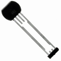
ATS642LSHTN-I2-T
Description
IC SENSOR GEAR TOOTH 4-SIP
Manufacturer
Allegro Microsystems Inc
Type
Special Purposer
Specifications of ATS642LSHTN-I2-T
Output Type
Digital, Open Collector
Sensing Range
120mV Trip, 120mV Release
Voltage - Supply
4 V ~ 24 V
Current - Supply
8.4mA
Features
Gear Tooth Type
Operating Temperature
-40°C ~ 150°C
Package / Case
4-SIP
Termination Type
Through Hole
Bandwidth
40kHz
Current Rating
16.8mA
Operate Point Max
1000G
Supply Voltage Max
24V
Leaded Process Compatible
Yes
No. Of Pins
4
Hall Effect Type
Gear Tooth
Supply Voltage Min
4V
Rohs Compliant
Yes
Filter Terminals
Through Hole
Operate Point Min
30G
Lead Free Status / RoHS Status
Lead free / RoHS Compliant
Current - Output (max)
-
Lead Free Status / RoHS Status
Lead free / RoHS Compliant, Lead free / RoHS Compliant
Available stocks
Company
Part Number
Manufacturer
Quantity
Price
Company:

Part Number:
ATS642LSHTN-I2-T
Manufacturer:
ALLEGRO
Quantity:
7 200


ATS642LSH
Sensor Operation
Each operating mode is described in detail below.
Power-On
When power (V
period of time is required to power the various portions of the
IC. During this period, the ATS642 will power-on in the high
current state, I
could induce a change in the output state. Such an event could be
caused by thermal transients, but would require a static applied
magnetic field, proper signal polarity, and particular direction
and magnitude of internal signal drift.
Initial Offset Adjust
The sensor intially cancels the effects of chip, magnet, and
installation offsets. Once offsets have been cancelled, the digital
tracking DAC is ready to track the signal and provide output
switching. The period of time required for both Power-On and
Initial Offset Adjust is defined as the Power-On Time.
Calibration Mode
The calibration mode allows the sensor to automatically select
the proper signal gain and continue to adjust for offsets. The
Figure 9: Operation of Running Mode Gain Adjust.
Position 1. The device is initially powered-on. Self-calibration occurs.
Position 2. Small amplitude oscillation of the target sends an erroneously small differential signal to the sensor. The ampli-
tude of V
Position 3. The calibration period completes on the third rising output edge, and the device enters Running mode.
Position 4. True target rotation occurs and the correct magnetic signal is generated for the installation air gap. The estab-
lished signal gain is too large for the target’s rotational magnetic signal at the given air gap.
Position 5. Running Mode Calibration corrects the signal gain to an optimal level for the installation air gap.
Internal Differential
Signal, V
Sensor Electrical
Output, I
CC(High)
CC
> V
PROC
. After power on, there are conditions that
OUT
PROC
CCMIN
is greater than the switching hysteresis (B
) is applied to the device, a short
Peak-Detecting Gear Tooth Sensor with Continuous Calibration
1
2
B
OP
B
Two-Wire True Zero Speed Miniature Differential
RP
OP
and B
3
AGC is active, and selects the optimal signal gain based on the
amplitude of the V
the AGC DAC, the Offset DAC is also adjusted to ensure the
internal analog signal is properly centered.
During this mode, the tracking DAC is active and output switch-
ing occurs, but the duty cycle is not guaranteed to be within
specification.
Running Mode
After the Initial Calibration period, C
the device moves to Running mode. During Running mode, the
sensor tracks the input signal and gives an output edge for every
peak of the signal. AOA remains active to compensate for any
offset drift over time.
The ATS642 incorporates a novel algorithm for adjusting the
signal gain during Running mode. This algorithm is designed
to optimize the V
magnetic signal “seen” during the calibration period is not repre-
sentative of the amplitude of the magnetic signal for the installed
sensor air gap (see figure 9).
RP
), and the device output switches.
4
PROC
PROC
signal amplitude in instances where the
signal. Following each adjustment to
115 Northeast Cutoff
1.508.853.5000; www.allegromicro.com
Allegro MicroSystems, Inc.
Worcester, Massachusetts 01615-0036 U.S.A.
5
B
OP
B
RP
I
, establishes a signal gain,
13
Related parts for ATS642LSHTN-I2-T
Image
Part Number
Description
Manufacturer
Datasheet
Request
R

Part Number:
Description:
IC, HALL EFFECT SENSOR, Linear, SOIC-8
Manufacturer:
Allegro Microsystems Inc
Datasheet:
Part Number:
Description:
IC, HALL EFFECT SENSOR, Linear, SOIC-8
Manufacturer:
Allegro Microsystems Inc
Datasheet:
Part Number:
Description:
IC, HALL EFFECT SENSOR, Linear, SOIC-8
Manufacturer:
Allegro Microsystems Inc
Datasheet:

Part Number:
Description:
IC SWITCH INTERFACE 2CHAN 8-SOIC
Manufacturer:
Allegro Microsystems Inc
Datasheet:

Part Number:
Description:
IC SMOKE DETECTOR ION 16-DIP
Manufacturer:
Allegro Microsystems Inc
Datasheet:
Part Number:
Description:
IC SMOKE DETECTOR ION 16-DIP
Manufacturer:
Allegro Microsystems Inc
Datasheet:
Part Number:
Description:
IC SMOKE DETECTOR ION 16-DIP
Manufacturer:
Allegro Microsystems Inc
Datasheet:
Part Number:
Description:
IC SMOKE DETECTOR PHOTO 16-DIP
Manufacturer:
Allegro Microsystems Inc
Datasheet:
Part Number:
Description:
IC SMOKE DETECTOR ION 16-DIP
Manufacturer:
Allegro Microsystems Inc
Datasheet:
Part Number:
Description:
IC SMOKE DETECTOR PHOTO 16-DIP
Manufacturer:
Allegro Microsystems Inc
Datasheet:
Part Number:
Description:
IC SMOKE DETECTOR PHOTO 16-DIP
Manufacturer:
Allegro Microsystems Inc
Datasheet:
Part Number:
Description:
IC SMOKE DETECTOR ION 16-DIP
Manufacturer:
Allegro Microsystems Inc
Datasheet:
Part Number:
Description:
IC SMOKE DETECTOR PHOTO 16-SOIC
Manufacturer:
Allegro Microsystems Inc
Datasheet:

Part Number:
Description:
IC LED DRIVER HIGH BRIGHT 16-QFN
Manufacturer:
Allegro Microsystems Inc
Datasheet:

Part Number:
Description:
IC LED DRIVER AUTOMOTIVE 8-SOIC
Manufacturer:
Allegro Microsystems Inc
Datasheet: