ATS642LSHTN-I2-T Allegro Microsystems Inc, ATS642LSHTN-I2-T Datasheet
ATS642LSHTN-I2-T
Specifications of ATS642LSHTN-I2-T
Available stocks


Related parts for ATS642LSHTN-I2-T


ATS642LSHTN-I2-T Summary of contents
Page 1
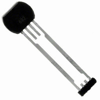
Two-Wire True Zero Speed Miniature Differential Peak-Detecting Gear Tooth Sensor with Continuous Calibration Features and Benefits ▪ Running mode calibration for continuous optimization ▪ Single chip IC for high reliability ▪ Internal current regulator for 2-wire operation ▪ Small mechanical ...
Page 2
... The 1.5 mm Hall element spacing is optimized for fine pitch gear-tooth-based configurations. The package is lead (Pb) free, with 100% matte tin leadframe plating. Selection Guide Part Number ATS642LSHTN-I1-T 6.0 Low to 14.0 High mA ATS642LSHTN-I2-T 7.0 Low to 14.0 High mA ® *Contact Allegro for additional packing options Absolute Maximum Ratings Characteristic ...
Page 3
ATS642LSH Peak-Detecting Gear Tooth Sensor with Continuous Calibration OPERATING CHARACTERISTICS using reference target 60-0, T Characteristic Symbol ELECTRICAL CHARACTERISTICS 2 Supply Voltage V CC Undervoltage Lockout V CC(UV) Supply Zener Clamp Voltage V Supply Zener Current I I CC(Low) Supply ...
Page 4
ATS642LSH Peak-Detecting Gear Tooth Sensor with Continuous Calibration OPERATING CHARACTERISTICS (continued) using reference target 60-0, T Characteristic SWITCHPOINT CHARACTERISTICS Rotation Speed Analog Signal Bandwidth Operate Point Release Point CALIBRATION Initial Calibration DAC CHARACTERISTICS Allowable User-Induced Differential Offset 6 FUNCTIONAL CHARACTERISTICS ...
Page 5
ATS642LSH Peak-Detecting Gear Tooth Sensor with Continuous Calibration REFERENCE TARGET, 60-0 (60 Tooth Target) Characteristics Symbol Outside Diameter D o Face Width F Angular Tooth Thickness t Angular Valley Thickness t v Tooth Whole Depth h t Material Reference Gear ...
Page 6
ATS642LSH Peak-Detecting Gear Tooth Sensor with Continuous Calibration Supply Current (High) versus Ambient Temperature (ATS642-I1 - (°C) A Supply Current (Low) versus Ambient Temperature (ATS642- I1 -50 ...
Page 7
ATS642LSH Peak-Detecting Gear Tooth Sensor with Continuous Calibration *The trend of duty cycle versus air gap is driven by the actual magnetic profile of the target (see figure on page 5). Duty Cycle versus Ambient Temperature ...
Page 8
ATS642LSH Peak-Detecting Gear Tooth Sensor with Continuous Calibration Characteristic Allowable Air Gap Movement The colored area in the chart above shows the region of allow- able air gap movement within which the sensor will continue output switching. The output duty ...
Page 9
ATS642LSH Peak-Detecting Gear Tooth Sensor with Continuous Calibration THERMAL CHARACTERISTICS may require derating at maximum conditions, see application information Characteristic Package Thermal Resistance *Additional information is available on the Allegro Web site. Two-Wire True Zero Speed Miniature Differential Symbol Test ...
Page 10
ATS642LSH Peak-Detecting Gear Tooth Sensor with Continuous Calibration Sensing Technology The gear tooth sensor subassembly contains a single-chip dif- ferential Hall effect sensor IC, an optimized samarium cobalt magnet, and a flat ferrous pole piece. The Hall IC possesses two ...
Page 11
ATS642LSH Peak-Detecting Gear Tooth Sensor with Continuous Calibration Automatic Gain Control (AGC) This feature allows the device to operate with an optimal internal electrical signal, regardless of the air gap (within the AG speci- fication). During calibration, the device determines ...
Page 12
ATS642LSH Peak-Detecting Gear Tooth Sensor with Continuous Calibration Power Supply Protection The device contains an on-chip regulator and can operate over a wide V range. For devices that need to operate from an CC unregulated power supply, transient protection must ...
Page 13
ATS642LSH Peak-Detecting Gear Tooth Sensor with Continuous Calibration Sensor Operation Each operating mode is described in detail below. Power-On When power (V > applied to the device, a short CC CCMIN period of time is required to ...
Page 14
ATS642LSH Peak-Detecting Gear Tooth Sensor with Continuous Calibration The device must be operated below the maximum junction temperature of the device Under certain combinations of J(max) peak conditions, reliable operation may require derating sup- plied power or improving ...
Page 15
ATS642LSH Peak-Detecting Gear Tooth Sensor with Continuous Calibration F 0.75 8.00±0.05 5.80±0.05 E1 1.70±0.10 4.00±0.10 5.00±0. 24.65±0.10 13.10±0.10 A Two-Wire True Zero Speed Miniature Differential Package SH Module F 0.75 Branded E2 Face 0.71±0.05 0.60±0.10 ...
Page 16
ATS642LSH Peak-Detecting Gear Tooth Sensor with Continuous Calibration Copyright ©2004-2009, Allegro MicroSystems, Inc. The products described herein are manufactured under one or more of the following U.S. patents: 5,045,920; 5,264,783; 5,442,283; 5,389,889; 5,581,179; 5,517,112; 5,619,137; 5,621,319; 5,650,719; 5,686,894; 5,694,038; 5,729,130; ...