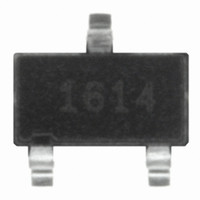
US1881ESE Melexis Inc, US1881ESE Datasheet - Page 12

US1881ESE
Manufacturer Part Number
US1881ESE
Description
IC LATCH CMOS MP TSOT23-3
Manufacturer
Melexis Inc
Type
Bipolar Latchr
Specifications of US1881ESE
Sensing Range
9.5mT Trip, -9.5mT Release
Voltage - Supply
3.5 V ~ 24 V
Current - Supply
5mA
Current - Output (max)
50mA
Output Type
Digital, Open Drain
Operating Temperature
-40°C ~ 85°C
Package / Case
TSOT-23-3, TSOT-3
Lead Free Status / RoHS Status
Lead free / RoHS Compliant
Features
-
Other names
US1881ESETR
linearly the number of dipoles aligning decreases. The result is a shallow slope to the function curve. At some
point, related to the material properties, increases in current through the magnetizing coil will not increase the
value of the field in the magnet. This is the saturation value for the material. When the external magnetizing
field is removed the magnetic field value of the sample "relaxes" to a steady state known as the B r value, or resid-
ual flux value.
An analogy to charging a battery is appropriate. At some level the battery is fully charged and will not accept
any more energy. It is an amazing thing however that the magnet will never lose its charge unless it is subjected
to a larger field of opposite polarity, or if the temperature is raised above the point known as the Curie
Temperature. This temperature varies depending on the material and is specified in all manufacturers data
sheets.
In summary we have discussed two of the three forces at work, one the magnetizing force measured in oersteds
with cgs units or ampere turns/meter in the SI system. The second is the resultant or induced field in the sample,
this is measured with gauss in cgs units and Teslas in the SI system (see Tables 1 and 2, below).
Table 1, Magnetic Units Comparison
Table 2, Magnetic Units Conversion
The third is reluctance or its' reciprocal permeability, think of this as the magnetic resistance per unit volume of
the sample being magnetized. Now that we have a magnetized magnet we can consider what occurs when forces
act to de-magnetize it. If we reverse the direction of current flow in the magnetizing coil a negative field is cre-
ated. As the negative current is increased the dipole alignment is reversed or undone. A curve results which is
similar to the magnetizing curve but in mirror image form. When the samples' flux value is completely demag-
netized the demagnetizing force at that instant is the coercive force -HC. This force is also measured like the
magnetizing force in Oersteds. Increasing the negative current level in the magnetizing coil.
Unit
Multiply
Gauss
Gauss
Oersteds
Flux
Flux Density
Magnetizing Force
lines/in
lines/in
Ampere turns/in
Ampere turns/in
2
2
Symbol
B
H
1.55 x 10
10
By
0.155
6.45
0.495
39.37
79.577
-4
-5
cgs System
Gauss
Oersted
Maxwell
Gauss
Oersteds
To obtain
Tesla
lines/in
Tesla
Ampere turns/m
Ampere turns/m
SI System
ampere turns/m
weber
Tesla
2
English System
Maxwell
lines/in
ampere turns/in
2


