61-1110.0 EAO, 61-1110.0 Datasheet - Page 51
61-1110.0
Manufacturer Part Number
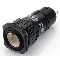
61-1110.0
Description
Switch Actuator
Manufacturer
EAO
Datasheet
1.61-1110.0.pdf
(76 pages)
Specifications of 61-1110.0
Mounting Hole Dia
16mm
Collar Shape
Round
Switch Operation
(ON)
Actuator Style
Round
For Use With
61 Series Illuminated Pushbutton Switches
Lead Free Status / RoHS Status
Lead free / RoHS Compliant


Application guidelines
When switching inductive loads such as relays, DC motors, and DC solenoids, it is always important to absorb surges (e.g. with a diode) to protect
the contacts. When these inductive loads are switched off, a counter emf can severely damage switch contacts and greatly shorten lifetime.
Fig. 1 shows an inductive load with a free-wheeling diode connected in parallel. This free-wheeling diode provides a path for the inductor current
to flow when the current is interrupted by the switch. Without this free-wheeling diode, the voltage across the coil will be limited only by dielectric
breakdown voltages of the circuit or parasitic elements of the coil. This voltage can be kilovolts in amplitude even when nominal circuit voltages
are low (e.g. 12 VDC) see Fig. 2.
The free-wheeling diode should be chosen so that the reverse breakdown voltage is greater than the voltage driving the inductive load. The DC
blocking voltage (VR) of the free-wheeling diode can be found in the datasheet of a diode. The forward current should be equal or greater than the
maximum current flowing through the load.
To get an efficient protection, the free-wheeling diode must be connected as close as possible to the inductive load!
0
VDC
Suppressor circuits
+
_
Switching with inductive load
Free-wheeling
Fig. 1
Switch
diode
Inductive
load
over load without free-wheeling diode
Sveral hundred
thousend volts
to several
Counter emf
0
Fig. 2
ON
OFF
e = L
__
dt
di
11.2009
49
61
Related parts for 61-1110.0
Image
Part Number
Description
Manufacturer
Datasheet
Request
R

Part Number:
Description:
Keylock Switch
Manufacturer:
EAO
Datasheet:

Part Number:
Description:
Key Operated Switch
Manufacturer:
EAO
Datasheet:

Part Number:
Description:
Switch Acuator
Manufacturer:
EAO
Datasheet:

Part Number:
Description:
Switch Actuator
Manufacturer:
EAO
Datasheet:
Part Number:
Description:
Switch Actuator
Manufacturer:
EAO
Datasheet:


Part Number:
Description:
Switch Actuator
Manufacturer:
EAO
Datasheet:

Part Number:
Description:
Switch Actuator
Manufacturer:
EAO
Datasheet:
Part Number:
Description:
Switch Actuator
Manufacturer:
EAO
Datasheet:
Part Number:
Description:
Switch Actuator
Manufacturer:
EAO
Datasheet:

Part Number:
Description:
Lens; 18 x 18 mm; 61 Series; Square; Plastic
Manufacturer:
EAO Switch
Datasheet:
Part Number:
Description:
Lens; Nickel and Chrome Plating; 18 mm; 61 Series; Round
Manufacturer:
EAO Switch
Datasheet:
Part Number:
Description:
Lens; 18 mm; 61 Series; Round; Plastic
Manufacturer:
EAO Switch
Datasheet:
Part Number:
Description:
Lens; Plastic; 61 Series, 18mm; YELLOW Transparent; Round; Raised Mount.; Flush
Manufacturer:
EAO Switch
Datasheet:
Part Number:
Description:
Lens; 18 x 18 mm; 61 Series; Square; Plastic
Manufacturer:
EAO Switch
Datasheet: