61-1110.0 EAO, 61-1110.0 Datasheet - Page 46
61-1110.0
Manufacturer Part Number
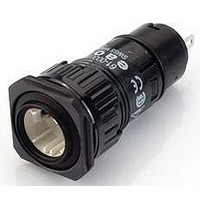
61-1110.0
Description
Switch Actuator
Manufacturer
EAO
Datasheet
1.61-1110.0.pdf
(76 pages)
Specifications of 61-1110.0
Mounting Hole Dia
16mm
Collar Shape
Round
Switch Operation
(ON)
Actuator Style
Round
For Use With
61 Series Illuminated Pushbutton Switches
Lead Free Status / RoHS Status
Lead free / RoHS Compliant


Technical Data
Environmental conditions
Approvals
>
Switching system
Material
Actuator with slow-make switching element
Storage temperature
-40 °C ... +85 °C
Operating temperature
-25 °C ... +55 °C
Protection degree
as per EN IEC 60529
Frontside IP 65 | backside IP 40
Shock resistance
(semi-sinusoidal)
max. 100 m/s², pulse width 11 ms, 3-axis, as per EN IEC 60068-2-
27
Vibration resistance
(sinusoidal)
max. 100 m/s² at 10 Hz ... 500 Hz, as per EN IEC 60068-2-6
Climate resistance
Damp heat, cyclic
96 hours, +25 °C / 97 %, +55 °C / 93 % relative humidity, as per EN
IEC 60068-2-30
Damp heat, state
56 days, +40 °C / 93 % relative humidity, as per EN IEC 60068-2-78
Rapid change of temperature
100 cycles, -40 °C ... +80 °C, as per EN IEC 60068-2-14
Approbations
CB (IEC 61058)
CB (IEC 60947)
CSA
ENEC (EN 61058)
Germanischer Lloyd
GOST
UL
VDE
Declaration of conformity
CE
Double-break slow-make system, contact opening width 2 x 1.5
mm, with 2 x 2 contact points per switching element.
NC-contact elements in the slow-make elements fulfill requirements
of switches with forced opening as per EN IEC 60947-5-1 2.17
The slow-make elements are optionally obtainable with the
following switching functions : 1 NO or 2 NO, 1 NC or 2 NC, 1 NO +
1 NC.
Lens
Raised mounting Polymethylmethacrylat (PMMA), as per UL 94
HB, flush mounting Polycarbonat (PC), as per UL 94 V0, or
Aluminium anodized
Front bezel
Polyetherimid (PEI), as per UL 94 V0, or Aluminium anodized
44
11.2009
Mechanical characteristics
0
0
0
0
0
0
0
Electrical characteristics
0
Front ring
Aluminium anodized
Material of contact
Silver or gold (specified for operation for low level switching)
Switching element
Diallylphthalate (DAP), as per UL 94 V0 and Polyamide (PA 66), as
per UL 94 V0
Actuator housing
Polyetherimide (PEI), as per UL 94 V0, self-extinguishing
Terminals
- Solder
1 wire
2 wires
- Screw
1 wire
2 wires
Actuating torque
Selector-/ Keylock switch
Actuating force
Pushbutton
Emergency-stop switch
Actuating travel
Pushbutton
Emergency-stop switch
Selector-/ keylock switch
Momentary action
Maintained action
Rebound time
2 ms, contact making and contact breaking
the rebound times apply to normal manual activation
Mechanical lifetime
as per DIN IEC 60512-5-6 and EN IEC 60947-5-1
Pushbutton maintained action
Pushbutton momentary action
Emergency-stop switch
Keylock switch
Selector switch
Standards
The devices comply with : EN IEC 61058-1 and EN IEC 60947-5-1,
EN IEC 60947-5-5 (Emergency-stop)
Electrical life
≥50.000 cycles of operation at 250 VAC, 5 A, cosφ 0.95, as per EN
IEC 60947-5-1
Switching Element of Emergency-stop 6050 cycles of operation, as
per EN IEC 60947-5-5
Electrostatic discharge (ESD)
Keylock switch
Electric strength
4000 VAC, 50 Hz, 1 min., as per DIN IEC 60512-2
between all terminals and earth
rigid
0.5 ... 1.5 mm²
0.75 mm²
0.5 ... 1.5 mm²
0.75 mm²
11 kV
3.5 ... 11 N
max. 65 N
3 mm
10 mm
2 positions
approx. 42 °
approx. 90 °
4 ... 16 Ncm
flexible
0.5 ... 0.75 mm²
0.5 mm²
0.5 ... 0.75 mm²
0.5 mm²
1 million
2 million
6 050
50 000
100 000
3 positions
approx. 2 x 42 °
approx. 2 x 90 °
cycles of operation
cycles of operation
cycles of operation
cycles of operation
cycles of operation
superflexible
0.5 mm²
0.5 mm²
0.5 mm²
61
Related parts for 61-1110.0
Image
Part Number
Description
Manufacturer
Datasheet
Request
R

Part Number:
Description:
Keylock Switch
Manufacturer:
EAO
Datasheet:

Part Number:
Description:
Key Operated Switch
Manufacturer:
EAO
Datasheet:

Part Number:
Description:
Switch Acuator
Manufacturer:
EAO
Datasheet:

Part Number:
Description:
Switch Actuator
Manufacturer:
EAO
Datasheet:
Part Number:
Description:
Switch Actuator
Manufacturer:
EAO
Datasheet:


Part Number:
Description:
Switch Actuator
Manufacturer:
EAO
Datasheet:

Part Number:
Description:
Switch Actuator
Manufacturer:
EAO
Datasheet:
Part Number:
Description:
Switch Actuator
Manufacturer:
EAO
Datasheet:
Part Number:
Description:
Switch Actuator
Manufacturer:
EAO
Datasheet:

Part Number:
Description:
Lens; 18 x 18 mm; 61 Series; Square; Plastic
Manufacturer:
EAO Switch
Datasheet:
Part Number:
Description:
Lens; Nickel and Chrome Plating; 18 mm; 61 Series; Round
Manufacturer:
EAO Switch
Datasheet:
Part Number:
Description:
Lens; 18 mm; 61 Series; Round; Plastic
Manufacturer:
EAO Switch
Datasheet:
Part Number:
Description:
Lens; Plastic; 61 Series, 18mm; YELLOW Transparent; Round; Raised Mount.; Flush
Manufacturer:
EAO Switch
Datasheet:
Part Number:
Description:
Lens; 18 x 18 mm; 61 Series; Square; Plastic
Manufacturer:
EAO Switch
Datasheet: