44-712 EAO, 44-712 Datasheet - Page 52
44-712
Manufacturer Part Number
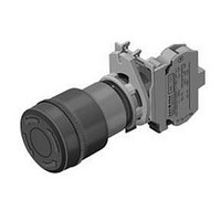
44-712
Description
Switch Actuator
Manufacturer
EAO
Datasheet
1.44-712.pdf
(84 pages)
Specifications of 44-712
Mounting Hole Dia
22.3mm
Mounting Type
Front Mount
For Use With
44 Series Emergency Stop Pushbutton Switches
Lead Free Status / RoHS Status
Lead free / RoHS Compliant


Technical Data
Switching system
Material
Mechanical characteristics
Electrical characteristics
Slow-make switching element
The double-break switching system can be supplied for the follo-
wing switching functions: 1 normally closed, 1 normally open or
1 changeover contact with or without overlap.
The normally closed contacts have forced opening according to
DIN 0660, IEC 60947-5-1 and DIN VDE 0113.
The switching element exhibits high reliability due to its H-contact
system with relative friction. The normally open and normally closed
contacts can be used electrically separated.
The standard version is ideal for high breaking capacities. For lower
capacities a special version can be supplied.
Material of contact
Standard version: Ag-Ni alloy
special version: Gold/Silver
Plastics
UL listed, Cd-free
Switching element
PC, PA 6.6 self-extinguishing
Actuating force
per switching element ≤5 N
Illuminated pushbutton actuator ≤10 N
Stop pushbutton actuator ≤20 N
Emergency-stop pushbutton actuator foolproof ≤70 N
Double pushbutton ≤12 N per contact surface
Actuating travel
approx. 6 mm
Mechanical lifetime
Slow-make switching element 10 x 10
Pushbutton momentary action 5 x 10
Pushbutton maintained action 1 x 10
Illuminated pushbutton momentary action 3 x 10
operations
Illuminated pushbutton maintained action 1 x 10
operation
Interlocking pushbutton 2 x 10
Stop pushbutton not foolproof 1 x 10
Emergency-stop foolproof >6050 cycles of operation
Keylock switch 2 x 10
Selector switch 2 x 10
Double pushbutton 2 x 10
Rated Insulation Voltage U
Slow-make switching element 660 V
Lamp element 250 V
Lamp transformer 660 V
Rated Operational Voltage U
AC 15 (inductive)
120 V, ~6 A
230 V, ~6 A
400 V, ~4 A
500 V, ~3 A
600 V, ~1.2 A
DC 13
50
03.2009
5
5
cycles of operation
cycles of operation
5
switching operations per contact surface
i
5
e
switching operations
5
6
6
6
cycles of operation
cycles of operation
switching operations
switching operations
6
6
cycles of
switching
0
0
Environmental conditions
24 V, 3 A
60 V, 1.3 A
120 V, 0.6 A
250 V, 0.3 A
Rated Impulse Withstand Voltage U
Lamp element 2,5 kV
Lamp transformer 6 kV
Slow-make switching element 6 kV*
* between the electrically separated normally closed contacts and
normally open contacts for slow-make switching elements.
1 NC + 1 NO without overlap
U
U
1 NC + 1 NO with overlap
U
U
Rated Operational Current I
AC-12 (resistive)
500 V, ~5 A
DC-12
24 V, 10 A
60 V, 8 A
125 V, 3 A
250 V, 1 A
Contact resistance
Starting value (initial) ≤50 mΩ
Electrical life
AC-15
400 V, ~2 A, 1 x 10
Conventional free air thermal current
lth
Short-circuit protection
max. series fuse to be provided 10 A gL
lamp transformer is short-circuit-proofed
Switch rating
Ag-Ni alloy
(Standard version)
Gold/Silver
(Special version)
Degree of pollution
3, as per EN IEC 60947-1
Storage temperature
-40 °C ... +70 °C
Operating temperature
-25 °C, as per EN IEC 60068-2-1
+60 °C, as per EN IEC 60068-2-2
Protection degree
Actuators at front and enclosure IP 65, as per EN IEC 60529
Shock resistance
40 g (duration 6 ms), as per EN IEC 60 68-2-27
Vibration resistance
sinusoidal, 5 g at 10-500 Hz, as per EN IEC 60068-2-6
e
imp
e
imp
2
>400 V, same polarity
>250 V, same polarity
= 10 A
= 4000 V
= 4000 V
6
minimal 5 V, 1 mA
maximum 42 V, 100 mA
switching operations
minimal 6 V, 20 mA
minimal 12 V, 10 mA
e
imp
44
Related parts for 44-712
Image
Part Number
Description
Manufacturer
Datasheet
Request
R


Part Number:
Description:
Indicator
Manufacturer:
EAO
Datasheet:


Part Number:
Description:
Switch Actuator
Manufacturer:
EAO
Datasheet:

Part Number:
Description:
Switch Actuator
Manufacturer:
EAO
Datasheet:
Part Number:
Description:
Switch Actuator
Manufacturer:
EAO
Datasheet:
Part Number:
Description:
Switch Actuator
Manufacturer:
EAO
Datasheet:

Part Number:
Description:
Incandescent Lamp
Manufacturer:
EAO
Datasheet:

Part Number:
Description:
SINGLE CHIP LED/ T1 BI-PIN/ 2.1VDC/20MA - RED
Manufacturer:
EAO
Datasheet:

Part Number:
Description:
INDICATOR, INCAND LAMP, BI PIN
Manufacturer:
EAO
Datasheet:

Part Number:
Description:
INDICATOR, BI-PIN
Manufacturer:
EAO
Datasheet:

Part Number:
Description:
INDICATOR, INCAND LAMP, MIDGET GROOVED
Manufacturer:
EAO
Datasheet: