MP240D4 OPTO 22, MP240D4 Datasheet - Page 12
MP240D4
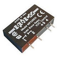
Manufacturer Part Number
MP240D4
Description
Solid State Relay
Manufacturer
OPTO 22
Specifications of MP240D4
Control Voltage Type
DC
Input Voltage
3VDC To 24VDC
Load Current
4A
Load Voltage Range
24VAC To 280VAC
Switching Mode
Zero Cross
Relay Terminals
Through Hole
Load Voltage Max
280VAC
Load Voltage Min
24VAC
Capacitance
8 pF (Max.) Coupling (Input-Output)
Current, Surge, Non-repetitive Peak
85 Apeak @ 1 Cycle
Dimensions
1.70 in. L x 0.40 in. W x 0.98 in. D
Control Voltage Max
32V
Control Voltage Min
3V
Rohs Compliant
Yes
Lead Free Status / RoHS Status
Lead free / RoHS Compliant
Available stocks
Company
Part Number
Manufacturer
Quantity
Price
Company:

Part Number:
MP240D4
Manufacturer:
CRYDOM
Quantity:
446
Company:
Part Number:
MP240D4
Manufacturer:
opto22
Quantity:
5 400
Company:
Part Number:
MP240D4 3-32VCD
Manufacturer:
OMRon
Quantity:
5 400
Company:
Part Number:
MP240D4-17 3-32VDC
Manufacturer:
opto22
Quantity:
5 400


DATA SHEET
Applications: Tips
Heat Sink Calculation
based on maximum junction temperature. All Opto 22 SSRs operate
conservatively at maximum junction temperatures of 110° C. Deter-
mining an adequate heat sink for a given SSR conducting a given
current is very simple.
relay base and the heat sink.
Sample Calculation Given
120-Volt, 20-Amp Load; 50° C Ambient Air
Choose Model 120D25 SSR.
Calculate dissipation as: 20 amps x 1.3 Watts per amp = 26 Watts
Calculate temperature rise junction to SSR base as: 26 Watts x 1.2° C per Watt = 31.2° C
Calculate allowable temperature of heat sink by subtracting 31.2° C from 110° C allowable junction temperature:
The heat sink is in a 50°C ambient, therefore, allowable temperature rise on heat sink is: 78.8° C-50° C = 28.8° C
If heat sink is allowed to rise 28.8° C above ambient, then the thermal resistance of the heat sink is simply the 28.8° C rise divided by
the 26 Watt. Any heat sink having a thermal resistance less than 1.1° C per Watt will be adequate.
Duty Cycle Calculation
When solid-state relays are operated in an on/off mode, it may be advantageous to calculate the RMS value of the current through the
SSR for heat sinking or determining the proper current rating of the SSR for the given application.
Form 859-050513
Dimension and specifications are subject to change. All products and/or company names throughout this data sheet are generally trademarks or registered trademarks of their respective companies.
I
RMS
T
T
I
Like all semiconductor devices, SSR current ratings must be
Note: Thermally conductive grease must be used between the
ON
1
2
Opto 22 • 43044 Business Park Drive • Temecula, CA 92590 • Phone: 951-695-3000 • 800-321-OPTO • Fax: 951-695-3095 • www.opto22.com
= Time current is on
= Time current is off
= RMS value of load current during on period
= RMS value of load or SSR
110° C-31.2 = 78.8° C
Inside Sales: 800-321-OPTO • E-mail: sales@opto22.com • Product Support: 800-TEK-OPTO • 951-695-3080 • Fax: 951-695-3017
I
RMS
SOLID-STATE RELAYS
=
(I
ON
T
)
1
2
+ T
x T
2
1
page 12/19
Related parts for MP240D4
Image
Part Number
Description
Manufacturer
Datasheet
Request
R

Part Number:
Description:
SSR, PANEL MOUNT, 280VAC, 32VDC, 10A
Manufacturer:
OPTO 22
Datasheet:

Part Number:
Description:
SSR, PANEL MOUNT, 280VAC, 32VDC, 25A
Manufacturer:
OPTO 22
Datasheet:
Part Number:
Description:
SSR, PANEL MOUNT, 280VAC, 32VDC, 25A
Manufacturer:
OPTO 22
Datasheet:
Part Number:
Description:
SSR, PANEL MOUNT, 280VAC, 32VDC, 45A
Manufacturer:
OPTO 22
Datasheet:
Part Number:
Description:
SSR, PANEL MOUNT, 280VAC, 32VDC, 45A
Manufacturer:
OPTO 22
Datasheet:

Part Number:
Description:
SSR, 10A, 240VAC
Manufacturer:
OPTO 22
Datasheet:

Part Number:
Description:
Programmable Logic Controller
Manufacturer:
OPTO 22
Datasheet:

Part Number:
Description:
Programmable Logic Controller
Manufacturer:
OPTO 22
Datasheet:

Part Number:
Description:
Solid State Relays, Accessories
Manufacturer:
OPTO 22
Datasheet:
