8952130000 Weidmuller, 8952130000 Datasheet - Page 93
8952130000
Manufacturer Part Number
8952130000
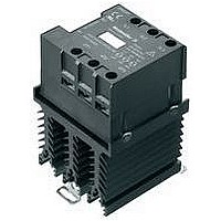
Description
SSR, DIN RAIL, 520VAC, 30VDC/30VAC, 20A
Manufacturer
Weidmuller
Datasheet
1.8952110000.pdf
(142 pages)
Specifications of 8952130000
Control Voltage Type
DC
Control Voltage Range
8VDC To 30VDC / 10VAC To 30VAC
Operating Voltage Range
24VAC To 520VAC
Peak Surge Current
250A
Load Current
20A
Switching Mode
Zero Cross
Rohs Compliant
No


Switching diverse loads
The different types of loads resulting from the possible applica-
tions (resistive, inductive, capacitive loads) represent a particular
challenge for the load circuit arrangements of opto modules and
solid-state relays. With reference to the planned application, one
should always be aware of what effects the loads will have on
the modules and how the corresponding protective devices
have to be designed.
Generally speaking, it must be ensured that the power loss at
the amplifier semiconductor does not exceed the permitted limit
for any length of time. This would lead to overheating and finally
to the destruction of the component.
Switching resistive loads
Due to the fact that in resistive loads the amperage in the load
circuit and the voltage across the amplifier semiconductor are
inversely proportional to one another these do not generally
pose a problem. It is sufficient to adhere to the maximum
current and voltage ratings of the modules.
Switching glow lamps represents a special case. It is possible
that when being switched on that overcurrents 10 to 20 times
the operating current can occur due to the low cold resistance.
Therefore, the components must be designed to cope with
these possible overloads situations which correspond to the
effect of capacitive loads.
Switching capacitive loads
Capacitive loads occur if there is a capacitor in the load circuit.
The effect is similar to to a short-circuit at the point of activation
and results in a high inrush current.
If this current is not limited it can lead to the destruction of the
amplifier semiconductor.
Switching inductive loads
Problems can arise with inductive loads when they are being
switched off, in particular when coils are used in the load circuit.
The flow of current in the coil builds up a magnetic field that
suddenly collapses and creates a high induction voltage.
This voltage spike has to be short-circuited via a diode
connected in parallel (free-wheeling diode). However, the time
required leads to delayed release.
Switching on
capacitive loads
Turning off
inductive loads
Operating voltage
Operating current
0 A
0 A
Switch-on point
Switch-off point
Optos – overview
Time
Time
C.93
C
Related parts for 8952130000
Image
Part Number
Description
Manufacturer
Datasheet
Request
R


Part Number:
Description:
STANDARD I.C. PIN
Manufacturer:
Mill-Max Manufacturing Corp.

Part Number:
Description:
MK 3/6
Manufacturer:
Weidmuller
Datasheet:
Part Number:
Description:
SL 5.08/7/90 3.2SN OR Omnimate Range 5.08
Manufacturer:
Weidmuller
Datasheet:
Part Number:
Description:
SL 5.08/18/90 3.2SN OR Omnimate Range 5.00/5.08
Manufacturer:
Weidmuller
Part Number:
Description:
SL 5.08/24/90 3.2SN OR Omnimate Range 5.00/5.08
Manufacturer:
Weidmuller