NC4D JP 12VDC PANASONIC EW, NC4D JP 12VDC Datasheet - Page 7
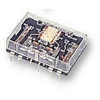
NC4D JP 12VDC
Manufacturer Part Number
NC4D JP 12VDC
Description
RELAY, PCB, 4PCO, 12VDC
Manufacturer
PANASONIC EW
Datasheet
1.NC2D_JP_12VDC.pdf
(11 pages)
Specifications of NC4D JP 12VDC
Relay Type
General Purpose
Coil Voltage Vdc Nom
12V
Contact Current Max
5A
Contact Voltage Ac Nom
250V
Coil Resistance
200ohm
Coil Type
DC Coil, Monostable
Nom Operating Power
720mW
Relay Mounting
PC
Contact Configuration
4PCO
Rohs Compliant
Yes
Lead Free Status / RoHS Status
Lead free / RoHS Compliant


Coil voltage
(
(
Schematic
— Energize relays only in the polarities shown —
1. Single side stable
Same operation as conventional magnetic relays.
Contacts will transfer only when coil is energized under indicated polarity.
2. 2 coil latching
Contacts will transfer only when coil is energized under indicated polarity.
Once transferred, contacts remain in that position even with power off until opposite coil is energized at indicated polarity.
Diagrams show the “set” position when
terminals 4 (–) and 5 (+) are energized.
When the coil current is switched off,
these contacts remain in “make” position.
REFERENCE DATA
Standard type
1.-(1) Life curve
DC load (2C, 4C)
2.-(1) Temperature rise characteristics for
single side stable
Measured portion: Inside the coil
en_ds_61135_0000: 310105J
2C : up to
2C : 100 V DC
4C : all types
2C
2C
48 V DC
Operating
power
10,000
1,000
100
80
70
60
50
40
30
20
)
)
220 V DC resistive
100 120 140 160
Reset
0.4 0.6 0.8 1.0 1.2 1.4 1.6 1.8W
set
110 V DC resistive
Contact carrying current, A
100 110 120 130 140 150%V
0.1
30 V DC resistive
180
4C
1.0
200
4C
2C
220%V
10
Reset
set
Energize terminals 3 (–) and 6 (+) to
transfer the contacts.
Diagrams show the “reset” position when
terminals 3 (–) and 6 (+) are energized.
AC load (2C)
2.-(2) Temperature rise characteristics for 2 coil
latching
Measured portion: Inside the coil
5,000
1,000
70
60
50
40
30
20
10
100
0
10
0
5 A (Max. contact carring current)
5
1
0 A (No. contact carring current)
4C
Contact carrying current, A
Energizing time, min.
2
5 A (Max. contact carring current)
0 A (No. contact carring current)
10
250 V AC resistive
250 V AC inductive (pf=0.4)
3
15
4
2C
4C
2C
20
5
25
Reset
set
Energize terminals 4 (–) and 5 (+) to
transfer the contacts.
AC load (4C)
5,000
1,000
100
10
0
4C
1
Contact carrying current, A
2
125 V AC resistive
250 V AC resistive
125 V AC inductive (pf=0.4)
250 V AC inductive (pf=0.4)
Reset
set
3
deenergized coil
energized coil
4
5
NC
7
Related parts for NC4D JP 12VDC
Image
Part Number
Description
Manufacturer
Datasheet
Request
R

Part Number:
Description:
POWER RELAY, 12VDC, 5A, 4PDT, PCB
Manufacturer:
PANASONIC EW
Datasheet:
Part Number:
Description:
POWER RELAY, 4PDT, 24VDC, 4A, PC BOARD
Manufacturer:
PANASONIC EW
Datasheet:

Part Number:
Description:
RELAY POWER 5A 24VDC VERT PLUGIN
Manufacturer:
Panasonic Electric Works
Datasheet:

Part Number:
Description:
RELAY PWR 5A 4PDT 5VDC FLAT PCB
Manufacturer:
Panasonic Electric Works
Datasheet:

Part Number:
Description:
RELAY POWER 5A 12VDC VERT PCB
Manufacturer:
Panasonic Electric Works
Datasheet:

Part Number:
Description:
RELAY POWER 5A 5VDC VERT PCB
Manufacturer:
Panasonic Electric Works
Datasheet:

Part Number:
Description:
RELAY PWR 5A 4PDT 24VDC VERT PCB
Manufacturer:
Panasonic Electric Works
Datasheet:
Part Number:
Description:
RELAY POWER 5A 12VDC VERT PLUGIN
Manufacturer:
Panasonic Electric Works
Datasheet:
Part Number:
Description:
RELAY POWER 5A 5VDC VERT PLUG-IN
Manufacturer:
Panasonic Electric Works
Datasheet:
Part Number:
Description:
RELAY POWER 5A 6VDC VERT PLUG-IN
Manufacturer:
Panasonic Electric Works
Datasheet:

Part Number:
Description:
SIGNAL RELAY, DPDT, 5VDC, 2A, PC BOARD
Manufacturer:
PANASONIC EW
Datasheet:


Part Number:
Description:
PHOTOMOS RELAY, 60VDC, 400mA
Manufacturer:
PANASONIC EW
Datasheet:

Part Number:
Description:
PHOTOMOS RELAY, 400V, 150mA
Manufacturer:
PANASONIC EW
Datasheet: