RM4TG20 TELEMECANIQUE, RM4TG20 Datasheet - Page 23
RM4TG20
Manufacturer Part Number
RM4TG20
Description
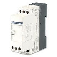
PHASE MONITORING RELAY, DPDT-2CO, 484VAC
Manufacturer
TELEMECANIQUE
Series
RM4r
Datasheet
1.RM4TG20.pdf
(30 pages)
Specifications of RM4TG20
Contact Configuration
DPCO
Phase Type
3 Phase
Supply Voltage Max
484VAC
Switching Voltage Max
440VAC
Relay Mounting
DIN Rail
Length/height, External
78mm
External Width
22.5mm
External Depth
80mm
Carry Current
8A
Available stocks
Company
Part Number
Manufacturer
Quantity
Price
Company:

Part Number:
RM4TG20
Manufacturer:
PANASONIC
Quantity:
45 000


3
Characteristics :
page 3/51
References :
page 3/52
Dimensions, schemes :
page 3/53
RM4-UB
3/50
Te
Zelio Control - measurement and control relays
Single-phase supply control relays RM4-UB
Presentation
Functions
These devices are designed for monitoring single-phase mains and power supplies.
They have a transparent, hinged flap on their front face to prevent any accidental alteration of the settings.
The flap can be directly sealed.
Applications
- Protection of electronic or electromechanical devices against overvoltage and undervoltage.
- Normal/emergency power supply switching.
Presentation
RM4-UB
1
2
3
4
R
U
> U Red LED: overvoltage fault
< U Red LED: undervoltage fault
Operating principle
The supply voltage to be monitored is connected to terminals L1, L3 of the product.
There is no need to provide a separate power supply for RM4-UB relays; they are self-powered by terminals L1, L2, L3.
If the voltage goes outside the range to be monitored, the output relay is de-energised:
- overvoltage: red LED “> U” illuminates.
- undervoltage: red LED “< U” illuminates.
When the supply returns towards its rated value, the relay is re-energised according to the hysteresis value (5%) and the
corresponding red LED goes out.
A selector switch allows selection of an adjustable time delay from 0.1 s to 10 s. With function
“under” voltages are not taken into account. With function
re-energisation of the relay is delayed.
In all cases, in order to be detected, the duration of the overvoltage or undervoltage must be greater than the measuring
cycle time (80 ms).
Function diagram
t: time delay
Function
Function
R
U
>U
<U
Overvoltage setting potentiometer.
Undervoltage setting potentiometer.
Time delay function selector:
Potentiometer for setting time delay in seconds.
Yellow LED: indicates relay state.
Green LED: indicates that supply to the RM4 is on.
RM4-UB34
RM4-UB35
0.95 x Setting > U
1.05 x Setting < U
Fault detection delayed.
Fault detection extended.
Setting > U
Setting < U
1
2
3
4
15/18 25/28
15/16 25/26
15/18 25/28
15/16 25/26
U
L1 L3
t
t
t
t
, all variations above or below are taken into account and
t
< t
t
< t
t
0 Volt
, transient “over” or
Related parts for RM4TG20
Image
Part Number
Description
Manufacturer
Datasheet
Request
R

Part Number:
Description:
Control Contactor
Manufacturer:
TELEMECANIQUE
Datasheet:

Part Number:
Description:
Control Contactor
Manufacturer:
TELEMECANIQUE
Datasheet:

Part Number:
Description:
Contactor
Manufacturer:
TELEMECANIQUE
Datasheet:

Part Number:
Description:
Contactor
Manufacturer:
TELEMECANIQUE
Datasheet:
Part Number:
Description:
Control Contactor
Manufacturer:
TELEMECANIQUE
Datasheet:

Part Number:
Description:
CONTACTOR, 2NO/2NC, 9A, 230VAC
Manufacturer:
TELEMECANIQUE
Datasheet:

Part Number:
Description:
Contactor
Manufacturer:
TELEMECANIQUE
Datasheet:

Part Number:
Description:
CONTACTOR, 4KW, 400VAC
Manufacturer:
TELEMECANIQUE
Datasheet:

Part Number:
Description:
CONTACTOR, 5.5KW, 230VAC
Manufacturer:
TELEMECANIQUE
Datasheet:
Part Number:
Description:
CONTACTOR, 5.5KW, 400VAC
Manufacturer:
TELEMECANIQUE
Datasheet:

Part Number:
Description:
RM, RM/I, RM/ILP cores and accessories
Manufacturer:
FERROXCUBE [Ferroxcube International Holding B.V.]
Datasheet:
Part Number:
Description:
RM, RM/I, RM/ILP cores and
Manufacturer:
FERROXCUBE [Ferroxcube International Holding B.V.]
Datasheet:
Part Number:
Description:
RM Bobbins
Manufacturer:
FERYSTER [FERYSTER Inductive Components Manufacturer]
Datasheet:

Part Number:
Description:
PILOT LIGHT HEAD, WHITE
Manufacturer:
TELEMECANIQUE
Datasheet:
Part Number:
Description:
LENS HEAD, BA 9S
Manufacturer:
TELEMECANIQUE
Datasheet: