RM4TG20 TELEMECANIQUE, RM4TG20 Datasheet - Page 10
RM4TG20
Manufacturer Part Number
RM4TG20
Description
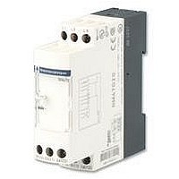
PHASE MONITORING RELAY, DPDT-2CO, 484VAC
Manufacturer
TELEMECANIQUE
Series
RM4r
Datasheet
1.RM4TG20.pdf
(30 pages)
Specifications of RM4TG20
Contact Configuration
DPCO
Phase Type
3 Phase
Supply Voltage Max
484VAC
Switching Voltage Max
440VAC
Relay Mounting
DIN Rail
Length/height, External
78mm
External Width
22.5mm
External Depth
80mm
Carry Current
8A
Available stocks
Company
Part Number
Manufacturer
Quantity
Price
Company:

Part Number:
RM4TG20
Manufacturer:
PANASONIC
Quantity:
45 000


Presentation :
pages 3/32 and 3/33
Characteristics :
page 3/34
References :
page 3/35
Dimensions, schemes :
page 3/36
Example of overcurrent to be measured
Overcurrent threshold at: 13 A.
Output relay time delay: 5 s.
Reset current threshold: 11 A.
Supply voltage: 127 V a.
Adjustments:
i Adjustment of function and timing range, switch
i Fine adjustment of time delay:
i Set the current threshold setting potentiometer
i Set the hysteresis
Extension of the measuring range
Application:
Use of relay RM4-JA31ii (10 to 100 mA).
Connection B2-C to measure a threshold of 1 A, knowing that Ri = 10
The value of Rs will be:
P = (1 -
Select a resistor Rs capable of dissipating at least twice the calculated value, i.e. 1 W for this example, in order to limit temperature rise.
On an a.c. supply, it is also possible to use a current transformer.
RM4-JA
R
U
- determine whether overcurrent or undercurrent detection is required; in this example, overcurrent.
- determine the timing range, immediately greater than the time required; in this example, 10 s.
- position switch
Depending on the max. range setting displayed at
In this example, the required time = 5 s therefore :
In this example: wiring B3-C, max. value of measuring range = 15 A, therefore:
Setting
Setting
t x 100
4
Ri
0.1
2
1
2
=
=
=
)
B1
5 x 100
2
C
x 0.526 i.e. 0.47 W
10
13 x 100
13 - 11
13
15
4
1
2
3
4
2
according to the above 2 criteria; in this example, switch
= 50 %
Im
as a % of the threshold value; in this example:
(2 x 1/0.1) - 1
= 15.4 %
= 87 %
10
Rs
I
= 0.526
Zelio Control - measurement and control relays
Current measurement relays RM4-JA
Setting-up
i Product selected RM4-JA32MW
d.c. or a.c. supply
Simply connect a resistor “Rs” to terminals B1-C (or B2, B3-C) on the measuring input.
The relay energisation threshold will be towards the middle of the setting potentiometer range if the value of Rs is in the
region of:
Rs =
Power dissipated by Rs: P = Rs (I -Im/2)
Connection of current to be measured B3-C (3 to 15 A)
Set the time delay potentiometer
Set the current threshold setting potentiometer
Set the hysteresis
(2I/Im) - 1
1
4
Ri
as a percentage of the maximum value of the measuring range selected when wiring.
:
4
(in this example: 10 s) use potentiometer
where : Ri Internal resistance of input B1-C.
2
to 15 (13 - 11 = 2 i.e. 15.4 % of the current to be measured).
Im Maximum value of threshold setting range.
I
Current threshold to be measured.
for this rating and that Im = 100 mA
3
to 50.
4
on > 10.
2
1
to 87.
3
to set the required time delay as a % of value 4.
Te
3/37
3
Related parts for RM4TG20
Image
Part Number
Description
Manufacturer
Datasheet
Request
R

Part Number:
Description:
Control Contactor
Manufacturer:
TELEMECANIQUE
Datasheet:

Part Number:
Description:
Control Contactor
Manufacturer:
TELEMECANIQUE
Datasheet:

Part Number:
Description:
Contactor
Manufacturer:
TELEMECANIQUE
Datasheet:

Part Number:
Description:
Contactor
Manufacturer:
TELEMECANIQUE
Datasheet:
Part Number:
Description:
Control Contactor
Manufacturer:
TELEMECANIQUE
Datasheet:

Part Number:
Description:
CONTACTOR, 2NO/2NC, 9A, 230VAC
Manufacturer:
TELEMECANIQUE
Datasheet:

Part Number:
Description:
Contactor
Manufacturer:
TELEMECANIQUE
Datasheet:

Part Number:
Description:
CONTACTOR, 4KW, 400VAC
Manufacturer:
TELEMECANIQUE
Datasheet:

Part Number:
Description:
CONTACTOR, 5.5KW, 230VAC
Manufacturer:
TELEMECANIQUE
Datasheet:
Part Number:
Description:
CONTACTOR, 5.5KW, 400VAC
Manufacturer:
TELEMECANIQUE
Datasheet:

Part Number:
Description:
RM, RM/I, RM/ILP cores and accessories
Manufacturer:
FERROXCUBE [Ferroxcube International Holding B.V.]
Datasheet:
Part Number:
Description:
RM, RM/I, RM/ILP cores and
Manufacturer:
FERROXCUBE [Ferroxcube International Holding B.V.]
Datasheet:
Part Number:
Description:
RM Bobbins
Manufacturer:
FERYSTER [FERYSTER Inductive Components Manufacturer]
Datasheet:

Part Number:
Description:
PILOT LIGHT HEAD, WHITE
Manufacturer:
TELEMECANIQUE
Datasheet:
Part Number:
Description:
LENS HEAD, BA 9S
Manufacturer:
TELEMECANIQUE
Datasheet: