XTMC9A10TD EATON CUTLER HAMMER, XTMC9A10TD Datasheet - Page 145
XTMC9A10TD
Manufacturer Part Number
XTMC9A10TD
Description
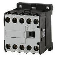
CONTACTOR SPST-NO, 24VDC, 8.8A, DIN RAIL
Manufacturer
EATON CUTLER HAMMER
Datasheet
1.XTCE007B10A.pdf
(312 pages)
Specifications of XTMC9A10TD
No. Of Poles
3
Contact Configuration
SPST-NO
Relay Mounting
DIN Rail
Coil Voltage Vdc Nom
24V
Relay Terminals
Screw Clamp
Nom Operating Power
4kW
Contact Voltage Ac Nom
690V
Operating Voltage
690VAC
Switching Power Ac1
1.5hp
Switching Power Ac3
5hp
Switching Current Ac1
20A
Switching Current Ac3
8.8A
Load Current Inductive
8.8A
Load Current Resistive
20A
Rohs Compliant
Yes
Lead Free Status / RoHS Status
Lead free / RoHS Compliant


March 2009
Time/Current Curve
Characteristics
The time/current characteristic, the current limiting charac-
teristics and the I
dance with DIN VDE 0660 and IEC 60 947.
The tripping characteristic of the inverse-time delayed over-
load releases (thermal overload releases or “a” releases) for
DC and AC with a frequency of 0 to 400 Hz also apply to the
time/current characteristic.
The characteristics apply to the cold state. At operating
temperature, the tripping times of the thermal releases are
reduced to approximately 25%.
Under normal operating conditions, all three poles of the
device must be loaded. The three main conducting paths
must be connected in series in order to protect single-phase
or DC loads.
With 3-pole loading, the maximum deviation in the tripping
time for 3 times the setting current and upwards is ±20% and
thus in accordance with DIN VDE 0165.
The tripping characteristics for the instantaneous, electro-
magnetic overcurrent releases (short-circuit releases or “n”
releases) are based on the rated current I n , which is also the
maximum value of the setting range for circuit-breakers with
adjustable overload releases. If the current is set to a lower
value, the tripping current of the “n” release is increased by
a corresponding factor.
The characteristics of the electromagnetic overcurrent
releases apply to frequencies of 50/60 Hz. Appropriate
correction factors must be used for lower frequencies up to
16-2/3 Hz, for higher frequencies up to 400 Hz and for DC.
Time/current characteristics, current limiting characteristics
and I
CA08102001E
2
t characteristics are available on request.
2
t characteristics were determined in accor-
For more information visit: www.eaton.com
IEC Contactors & Starters
XT IEC Power Control
Manual Motor Protectors
Figure 34-106. MMP Tripping Characteristics — XTPB, XTPR Frame B
and XTPT (not for XTPM)
Figure 34-107. MMP Tripping Characteristics — XTPR Frame D
200
200
2h
20
10
50
2h
20
10
50
20
10
40
20
20
10
40
20
5
2
1
5
2
1
5
2
5
2
1
5
2
1
5
2
1.5 2
1.5 2
x Rated Operational Current
x Rated Operational Current
3
3
4
4
XTPB, XTPR Frame B
6
6
8 10
8 10
XTPR Frame D
15 20
15 20
XTPT
30
30
34-145
34
Related parts for XTMC9A10TD
Image
Part Number
Description
Manufacturer
Datasheet
Request
R

Part Number:
Description:
PROGRAMMABLE LOGIC CONTROLLER
Manufacturer:
EATON CUTLER HAMMER
Part Number:
Description:
Pm Power Pro 3000/5000 A-B Accel/On Interface
Manufacturer:
EATON CUTLER HAMMER
Part Number:
Description:
Handle Tie Bar For (2) - 1 Pole Type BR Breakers
Manufacturer:
EATON CUTLER HAMMER
Part Number:
Description:
Type CH Breaker 150A/2 Pole 120/240V 10K
Manufacturer:
EATON CUTLER HAMMER
Part Number:
Description:
Tenant Branch Breaker 125A/3 Pole 120/240V 42K
Manufacturer:
EATON CUTLER HAMMER
Part Number:
Description:
Type CL Breaker 25A/1Pole 120/240V 10K-Classified 1" Ckt Bkr
Manufacturer:
EATON CUTLER HAMMER
Part Number:
Description:
FD BREAKER 1P 80 AMP WITH LOAD ONLY TERMINALS
Manufacturer:
EATON CUTLER HAMMER
Part Number:
Description:
GD 2 POLE BREAKER, 25 AMP, SINGLE PACKED
Manufacturer:
EATON CUTLER HAMMER
Part Number:
Description:
Handle Tie Bar For (2) - 1 Pole Type BR Breakers
Manufacturer:
EATON CUTLER HAMMER
Part Number:
Description:
Type CL Breaker 25A/1Pole 120/240V 10K-Classified 1" Ckt Bkr
Manufacturer:
EATON CUTLER HAMMER