XTCE012B10TD EATON CUTLER HAMMER, XTCE012B10TD Datasheet - Page 278
XTCE012B10TD
Manufacturer Part Number
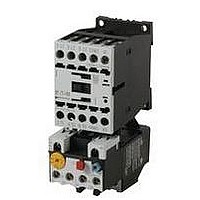
XTCE012B10TD
Description
CONTACTOR, SPST-NO, 24VDC, 12A, DIN RAIL
Manufacturer
EATON CUTLER HAMMER
Datasheet
1.XTCE007B10A.pdf
(312 pages)
Specifications of XTCE012B10TD
No. Of Poles
3
Contact Configuration
SPST-NO
Relay Mounting
DIN Rail
Coil Voltage Vdc Nom
24V
Relay Terminals
Screw Clamp
Nom Operating Power
6.5kW
Contact Voltage Ac Nom
690V
Operating Voltage
690VAC
Switching Power Ac1
2hp
Switching Power Ac3
10hp
Switching Current Ac1
22A
Switching Current Ac3
12A
Load Current Inductive
12A
Load Current Resistive
22A
Rohs Compliant
Yes
Lead Free Status / RoHS Status
Lead free / RoHS Compliant


34-278
34
Auxiliary Contact Location
NEMA Sizes 00 – 2, IEC Sizes A – K
The sketches below illustrate the maximum number of auxil-
iary contacts that can be assembled to a contactor or starter
and their locations.
Table 34-351. Auxiliary Contacts
Figure 34-167. Auxiliary Contact Location
Catalog
Number
AE16
AN16
AE56
AN56
CE15
CN15
CN35
CE55
CN55
Available positions on contactors or starters other than what is factory
installed.
When a pneumatic timer is mounted on contactor, only side mounted
auxiliary contact positions are available. The solid-state timer, when
added, takes up side mounted auxiliary contact position.
Contactors and Starters
IEC Contactors & Starters
Freedom
Accessories
L1
L1
Non-reversing
Front View
Top View
Size
A – K
00
0 – 2
A – K
00 – 2
A – C
D – K
G – J
G – J
00
0 – 2
1, 2
1, 2
10A
20 – 60A
60A
60A
A – K
00 – 2
T1
T1
R1
R1
Poles
3
3
3
3
3
2 – 4
3
4
5
2 – 4
2 – 3
4
5
2 – 4
2 – 3
4
5
3
3
L1
L1
Available Mounting Positions
Open Type
T1, L1
T1, L1, R1
T1, L1
L1, R1
T1, T2
T1, L1, R1
T1, L1
T1, R1
T1
T1, L1, R1
T1, L1
T1, L1
T1, L1
T1, L1, R1
T1, L1
T1, L1
T1, L1
L1, R1
T1, T2
Contactors and Starters
T1
T1
Front View
Reversing
Top View
For more information visit: www.eaton.com
Enclosed
L1
L1
L1
L1, R1
—
L1, R1
L1
—
—
L1
L1
—
—
L1
L1
—
—
L1, R1
—
T2
T2
R1
R1
NEMA Sizes 3 – 8, IEC Sizes L – Z
The sketches below illustrate the maximum number of auxil-
iary contacts that can be assembled to a contactor and their
locations.
Note: A Base Auxiliary Contact must be added in position R1 before
additional auxiliary contacts can be mounted on NEMA Size 3 and
IEC Sizes L – N, or in L1 on NEMA Sizes 4 – 5 and IEC Sizes P – S.
Table 34-352. Auxiliary Contacts
Figure 34-168. Auxiliary Contact Location
Size
NEMA Size 3, IEC Sizes L – N
NEMA Sizes 4 – 5, IEC Sizes P – S
NEMA Sizes 6 – 7, IEC Sizes T – X
NEMA Size 8, IEC Size Z
Available positions on contactors or starters other than what is factory
installed.
Cont.
Base
Aux.
L1
of Contactor
Left Side
Cont.
Aux.
L2
Cont.
Aux.
L3
L1
L2
IEC Sizes T, U, V, W and X
NEMA Sizes 3 – 5
NEMA Sizes 6 – 7
IEC Sizes L – S
L1
NEMA Size 8
of Contactor
IEC Size Z
Front
Available Mounting Positions
R2, R3, L1, L2, L3
L2, L3, R1, R2, R3
R1
L2, R2
R1
R1
R2
Cont.
Aux.
R3
of Contactor
Right Side
Cont.
Aux.
R2
CA08102001E
March 2009
Cont.
Base
Aux.
R1
Related parts for XTCE012B10TD
Image
Part Number
Description
Manufacturer
Datasheet
Request
R

Part Number:
Description:
PROGRAMMABLE LOGIC CONTROLLER
Manufacturer:
EATON CUTLER HAMMER
Part Number:
Description:
Pm Power Pro 3000/5000 A-B Accel/On Interface
Manufacturer:
EATON CUTLER HAMMER
Part Number:
Description:
Handle Tie Bar For (2) - 1 Pole Type BR Breakers
Manufacturer:
EATON CUTLER HAMMER
Part Number:
Description:
Type CH Breaker 150A/2 Pole 120/240V 10K
Manufacturer:
EATON CUTLER HAMMER
Part Number:
Description:
Tenant Branch Breaker 125A/3 Pole 120/240V 42K
Manufacturer:
EATON CUTLER HAMMER
Part Number:
Description:
Type CL Breaker 25A/1Pole 120/240V 10K-Classified 1" Ckt Bkr
Manufacturer:
EATON CUTLER HAMMER
Part Number:
Description:
FD BREAKER 1P 80 AMP WITH LOAD ONLY TERMINALS
Manufacturer:
EATON CUTLER HAMMER
Part Number:
Description:
GD 2 POLE BREAKER, 25 AMP, SINGLE PACKED
Manufacturer:
EATON CUTLER HAMMER
Part Number:
Description:
Handle Tie Bar For (2) - 1 Pole Type BR Breakers
Manufacturer:
EATON CUTLER HAMMER
Part Number:
Description:
Type CL Breaker 25A/1Pole 120/240V 10K-Classified 1" Ckt Bkr
Manufacturer:
EATON CUTLER HAMMER