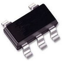
74HC1GU04GW NXP Semiconductors, 74HC1GU04GW Datasheet - Page 6

74HC1GU04GW
Manufacturer Part Number
74HC1GU04GW
Description
74HC SINGLE GATE, SMD, 74HC1GU04
Manufacturer
NXP Semiconductors
Datasheet
1.74HC1GU04GW.pdf
(16 pages)
Specifications of 74HC1GU04GW
Logic Type
Inverter Gate
Output Current
2.6mA
No. Of Inputs
1
Supply Voltage Range
2V To 6V
Logic Case Style
SOT-353
No. Of Pins
5
Operating Temperature Range
-40°C To +125°C
Svhc
No SVHC
Lead Free Status / RoHS Status
Lead free / RoHS Compliant
Philips Semiconductors
AC CHARACTERISTICS
GND = 0 V; t
Note
1. All typical values are measured at T
AC WAVEFORMS
2002 May 27
handbook, halfpage
t
PHL
SYMBOL
Inverter
(1) V
Fig.5
/t
PLH
Y output
A input
M
= 50%; V
The input (A) to output (Y) propagation
delays.
r
= t
propagation delay
A to Y
I
f
= GND to V
= 6.0 ns; C
PARAMETER
V M
V M
(1)
CC
t PHL
(1)
.
L
= 50 pF.
see Figs 5 and 6
WAVEFORMS
amb
TEST CONDITIONS
= 25 C.
t PLH
MNA046
2.0
4.5
6.0
V
6
CC
handbook, halfpage
(V)
Definitions for test circuit:
C
(See “AC characteristics” for values).
R
impedance Z
L
T
= Load capacitance including jig and probe capacitance.
= Termination resistance should be equal to the output
MIN. TYP.
GENERATOR
Fig.6 Load circuitry for switching times.
PULSE
o
10
7
6
40 to +85
of the pulse generator.
(1)
V I
T
90
18
15
MAX.
amb
( C)
R T
D.U.T.
V CC
MIN.
40 to +125
74HC1GU04
Product specification
V O
105
21
18
MAX.
C L
50 pF
MNA034
ns
ns
ns
UNIT


