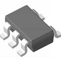
S-8550AA-M5T1G Seiko Instruments, S-8550AA-M5T1G Datasheet - Page 12

S-8550AA-M5T1G
Manufacturer Part Number
S-8550AA-M5T1G
Description
IC, SYNC STEP-DOWN REGULATOR, SOT-23-5
Manufacturer
Seiko Instruments
Datasheet
1.S-8550AA-M5T1G.pdf
(31 pages)
Specifications of S-8550AA-M5T1G
Primary Input Voltage
5.5V
No. Of Outputs
1
Output Voltage
4V
Output Current
600mA
No. Of Pins
5
Operating Temperature Range
-40°C To +85°C
Operating Temperature Min
85°C
Input Voltage
5.5 V
Duty Cycle (max)
100 %
Maximum Operating Temperature
+ 85 C
Mounting Style
SMD/SMT
Package / Case
SOT-23-5
Minimum Operating Temperature
- 40 C
Rohs Compliant
Yes
Lead Free Status / RoHS Status
Lead free / RoHS Compliant
Lead Free Status / RoHS Status
Lead free / RoHS Compliant
Available stocks
Company
Part Number
Manufacturer
Quantity
Price
Company:
Part Number:
S-8550AA-M5T1G
Manufacturer:
SEIKO
Quantity:
230
Part Number:
S-8550AA-M5T1G
Manufacturer:
SII/精工
Quantity:
20 000
12
STEP-DOWN, BUILT-IN FET, SYNCHRONOUS RECTIFICATION, PWM CONTROL SWITCHING REGULATORS
S-8550/8551 Series
External Parts Selection
1. Inductor
The inductance (L value) has a strong influence on the maximum output current (I
The peak current (I
L is decreased further, the current drive capability of the external transistor is insufficient and I
If the L value is increased, the loss due to I
maximum at a certain L value. Further increasing L decreases the efficiency due to the increased loss of the
DC resistance of the inductor.
The recommended L value for the S-8550/8551 Series is 3.3 μH.
When selecting an inductor, note the allowable current of the inductor. If a current exceeding this allowable
current flows through the inductor, magnetic saturation occurs, substantially lowering the efficiency.
Therefore, select an inductor so that I
following equations in the discontinuous mode and continuous mode.
f
OSC
Taiyo Yuden Co., Ltd.
Sumida Corporation
TDK Corporation
FDK Corporation
= Oscillation frequency
Manufacturer
I
PK
= I
OUT
PK
+
) increases by decreasing L and the stability of the circuit improves and I
V
2 × f
OUT
NR4018T3R3M
NR3012T3R3M
CDRH3D16/HP-3R3
CDRH2D11/HP-3R3
VLF4012AT-3R3M
VLF3010AT-3R3M
MIP3226D3R3M
MIPS2520D3R3M
× (V
OSC
Part Number
× L × V
IN
− V
Seiko Instruments Inc.
OUT
PK
IN
Table 8 Typical Inductors
)
does not exceed the allowable current.
PK
of the power MOS FET decreases and the efficiency becomes
L Value
3.3 μH
3.3 μH
3.3 μH
3.3 μH
3.3 μH
3.3 μH
3.3 μH
3.3 μH
0.085 Ω max.
0.173 Ω max.
0.104 Ω max.
0.156 Ω max.
0.07 Ω max.
0.12 Ω max.
0.17 Ω max.
Resistance
0.1 Ω max.
DC
Rated Current
1.23 A max.
0.91 A max.
1.40 A max.
0.87 A max.
0.9 A max.
1.3 A max.
1.2 A max.
1.0 A max.
OUT
) and efficiency (η).
I
PK
is expressed by the
OUT
(L × W × H) [mm]
OUT
4.0 × 4.0 × 1.8
3.0 × 3.0 × 1.2
4.0 × 4.0 × 1.8
3.2 × 3.2 × 1.2
3.7 × 3.5 × 1.2
2.6 × 2.8 × 1.0
3.2 × 2.6 × 1.0
2.5 × 2.0 × 1.0
Dimensions
decreases.
Rev.4.0
increases. If
_00


