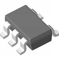
S-8550AA-M5T1G Seiko Instruments, S-8550AA-M5T1G Datasheet - Page 11

S-8550AA-M5T1G
Manufacturer Part Number
S-8550AA-M5T1G
Description
IC, SYNC STEP-DOWN REGULATOR, SOT-23-5
Manufacturer
Seiko Instruments
Datasheet
1.S-8550AA-M5T1G.pdf
(31 pages)
Specifications of S-8550AA-M5T1G
Primary Input Voltage
5.5V
No. Of Outputs
1
Output Voltage
4V
Output Current
600mA
No. Of Pins
5
Operating Temperature Range
-40°C To +85°C
Operating Temperature Min
85°C
Input Voltage
5.5 V
Duty Cycle (max)
100 %
Maximum Operating Temperature
+ 85 C
Mounting Style
SMD/SMT
Package / Case
SOT-23-5
Minimum Operating Temperature
- 40 C
Rohs Compliant
Yes
Lead Free Status / RoHS Status
Lead free / RoHS Compliant
Lead Free Status / RoHS Status
Lead free / RoHS Compliant
Available stocks
Company
Part Number
Manufacturer
Quantity
Price
Company:
Part Number:
S-8550AA-M5T1G
Manufacturer:
SEIKO
Quantity:
230
Part Number:
S-8550AA-M5T1G
Manufacturer:
SII/精工
Quantity:
20 000
STEP-DOWN, BUILT-IN FET, SYNCHRONOUS RECTIFICATION, PWM CONTROL SWITCHING REGULATORS
Rev.4.0
2. Backflow current
−113.5 mA
113.5 mA
The S-8550/8551 Series performs PWM synchronous rectification even if I
current is generated in V
11). Use the following equation to calculate the maximum backflow current value, which should be taken into
consideration when designing.
The current value waveform of the inductor is a triangular wave, of which the maximum value is I
minimum value is I
Figure 11) backflows when no load is applied (see Figure 11).
If about 113.5 mA of I
made 0 mA and no backflow current flows.
When an input capacitor (C
current to flow in the power supply. Be sure to connect an input capacitor to reduce backflow current to the
power supply (see Figure 12).
The above presents the conditions required to prevent backflow current from flowing, which is only a guideline.
Perform sufficient confirmation using an actual application.
_00
I
OUT
0 mA
Duty (I
ΔI
I
L
L
max. = ΔI
I
L
= ΔV / L × t
Inductor current with no load
Figure 11 Example of Conditions to Prevent Backflow Current from Flowing
OUT
= 0) = V
L
/ 2 = 113.5 mA, I
on
L
= (V
min. (negative value), and the negative value (the portion marked by diagonal lines in
V
OUT
OUT
IN
IN
IN
/ V
Example : V
Example : V
flows in the above conditions, the minimum value (I
IN
− V
and the backflow current becomes maximum when no load is applied (see Figure
) is connected, the backflow current is absorbed by C
C
IN
IN
OUT
ΔI
VIN
L
L
Backflow
current
I
) × Duty / (L × f
L
I
Figure 12 Backflow Current
min. = −ΔI
L
min.
max.
Seiko Instruments Inc.
IN
IN
= 3.6 V, V
= 3.6 V, V
L
/ 2 = −113.5 mA
OSC
OUT
OUT
)
113.5 mA
I
CONT
OUT
= 1.8 V …… Duty = 50%
= 1.8 V, f
227 mA
0 mA
Backflow current
Inductor
current I
I
L
Inductor current when load is a
current of 113.5 mA
OSC
= 1.2 MHz, L = 3.3 μH …… ΔI
L
V
L
OUT
min. is less than 0 A, so a backflow
Backflow current = 0 mA
L
min.) of the triangular wave is
IN
, thus reducing the backflow
S-8550/8551 Series
ΔI
L
I
I
L
L
min.
max.
L
L
= 227 mA
max. and the
11


