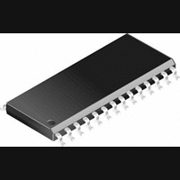
PIC14000-04I/SS Microchip Technology, PIC14000-04I/SS Datasheet - Page 26

PIC14000-04I/SS
Manufacturer Part Number
PIC14000-04I/SS
Description
IC, 8BIT MCU, PIC14, 4MHZ, SSOP-28
Manufacturer
Microchip Technology
Datasheet
1.PIC14000-04SO.pdf
(153 pages)
Specifications of PIC14000-04I/SS
Controller Family/series
PIC14
No. Of I/o's
22
Ram Memory Size
192Byte
Cpu Speed
4MHz
No. Of Timers
2
Interface
I2C
Digital Ic Case Style
SSOP
Core Size
8 Bit
Program Memory Size
4096 X 14
Embedded Interface Type
I2C
Rohs Compliant
Yes
Processor Series
PIC14000
Core
PIC
Data Bus Width
8 bit
Program Memory Type
EPROM
Data Ram Size
192 B
Interface Type
SPI, UART
Maximum Clock Frequency
20 MHz
Number Of Programmable I/os
22
Number Of Timers
1
Operating Supply Voltage
2.7 V to 6 V
Maximum Operating Temperature
+ 85 C
Mounting Style
SMD/SMT
Package / Case
SSOP-28
Development Tools By Supplier
ICE2000
Minimum Operating Temperature
- 40 C
On-chip Adc
14 bit
Lead Free Status / RoHS Status
Lead free / RoHS Compliant
PIC14000
FIGURE 5-2:
5.2
PORTC is a 8-bit wide bidirectional port, with Schmitt
Trigger inputs, that serves the following functions
depending on programming:
• Direct LED drive (PORTC<7:0>).
• I
• Interrupt on change function (PORTC<7:4>),
• Programmable reference and comparator
• Timer0 clock source on RC3
The PORTC data register is located at location 07h and
its data direction register (TRISC) is at 87h.
PORTC<5:0> have weak internal pull-ups (~100 uA
typical). A single control bit can turn on all the pull-ups.
This is done by clearing bit RCPU (OPTION<7>). The
weak pull-up is automatically turned off when the port
pin is configured as an output. The pull-ups are
disabled on power-on reset and in hibernate mode.
DS40122B-page 26
05h
PORTA
Read/Write
POR value 0xh
B7-B4
B3
B2
B1
B0
Section 7.0 I
discussed below and in Section 10.3 Interrupts.
outputs.
2
C communication lines (PORTC<7:6>), refer to
Bit
PORTC and TRISC
2
RA3/AN3
RA2/AN2
RA1/AN1
RA0/AN0
—
C Serial Port.
PORTA DATA REGISTER
Name
Bit 7
—
U
0
Function
Unimplemented. Reads as‘0’.
GPIO or analog input. Returns value on pin RA3/AN3 when used as a digital
input. When configured as an analog input, reads as ‘0’.
GPIO or analog input. Returns value on pin RA2/AN2 when used as a digital
input. When configured as an analog input, reads as ‘0’.
GPIO or analog input. Returns value on RA1/AN1 when used as a digital input.
This pin can connect to a level shift network. If enabled, a +0.5V offset is added
to the input voltage. When configured as an analog input, reads as ‘0’.
GPIO or analog input. Returns value on pin RA0/AN0 when used as a digital
input. When configured as an analog input, reads as ‘0’.
Bit 6
—
U
0
Bit 5
—
U
0
Preliminary
Bit 4
—
U
0
When using PORTC<0> as an analog output
(CMCON<1> bit is set), the TRISC<0> bit should be
cleared to disable the weak pull-up on this pin. Refer to
Table 5-1.
Four of the PORTC pins, RC<7:4> have an interrupt on
change feature. Only pins configured as inputs can
cause this interrupt to occur. In other words, any pin
RC<7:4> configured as an output is excluded from the
interrupt on change comparison. The input pins of
RC<7:4> are compared with the old value latched on
the last read of PORTC. The “mismatch” outputs of
RC<7:4> are OR’ed together to assert the RCIF flag
(PIR1 register<2>) and cause a CPU interrupt, if
enabled.
RA3/AN3
Note:
Bit 3
R/W
X
If
(I
automatically
interrupt-on-change comparison.
2
CCON<5>, address 14h), RC<7:6> are
RA2/AN2
the
Bit 2
R/W
X
I
2
C
1996 Microchip Technology Inc.
function
excluded
RA1/AN1
Bit 1
R/W
X
is
from
RA0/AN0
enabled,
Bit 0
R/W
X
the


