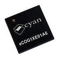
ECOG1XE01A6 CYAN, ECOG1XE01A6 Datasheet - Page 31

ECOG1XE01A6
Manufacturer Part Number
ECOG1XE01A6
Description
IC, 16BIT MCU, ECOG1X, 70MHZ, QFN-68
Manufacturer
CYAN
Datasheet
1.ECOG1X14Z5.pdf
(95 pages)
Specifications of ECOG1XE01A6
Controller Family/series
ECOG1X
No. Of I/o's
20
Ram Memory Size
8KB
Cpu Speed
70MHz
No. Of Timers
8
Digital Ic Case Style
QFN
Core Size
16 Bit
Program Memory Size
64KB
Embedded Interface Type
I2C, JTAG, SPI, UART
Rohs Compliant
Yes
Lead Free Status / RoHS Status
Lead free / RoHS Compliant
Analogue Input and Output
I
4 August 2009
2
S
The eCOG1X includes a flexible analogue control interface peripheral (ACI) providing analogue inputs
and outputs.
The main features of the Analogue Control Interface include:
•
•
•
•
•
•
•
•
•
•
•
•
•
•
•
The I
low pin count serial link for digital audio data. The eCOG1X I
slave capability, programmable data size and clock frequencies, and simultaneous bidirectional data
transfers.
The I
•
•
•
•
•
•
•
Two-channel successive approximation Analogue to Digital Converter (ADC).
Two-channel 12-bit Digital to Analogue Converter (DAC).
Internal 1.2V nominal bandgap voltage reference.
Analogue multiplexer with one internal and seven external input signals for each ADC.
Internal ADC inputs for temperature sensor and analogue supply voltage sensor.
Single-ended and differential input configurations.
Selectable ADC resolution of 6, 8, 10 or 12 bits.
Maximum conversion rates on each ADC channel:
•
•
•
•
Simultaneous sampling on the two ADC channels.
Sample/hold time can be increased for higher source impedances.
Automatic multiplexer channel scanning in hardware.
Interrupt on conversion scan complete.
Flexible software or hardware triggered conversion for both ADCs and DACs.
Analogue outputs settle to 12 bits accuracy within 4µs.
Power on reset circuit and low I/O supply voltage status bit.
Programmable data word size up to 32 bits for each channel.
Internal or external clock source.
•
•
Master or slave mode.
•
•
Master clock output, required by some CODECs for oversampling and digital filtering.
•
Programmable divider for bit clock SCLK.
•
•
•
Word select clock WS is set according to the number of data bits selected.
•
Programmable clock and data signal polarities.
2
2
S (Inter-IC Sound) standard bus was developed by Philips Semiconductors to provide a simple,
S peripheral has the following main features.
200ks/s at 12 bits resolution.
350ks/s at 10 bits resolution.
500ks/s at 8 bits resolution.
800ks/s at 6 bits resolution.
Internal clock source is set in the SSM.
Alternate clock input supports frequencies that cannot be achieved by the SSM.
The master device outputs SCLK and WS to the slave device.
Selection of master or slave mode is independent of the clock source selection.
MCLK frequency = selected input clock frequency.
SCLK is divided down from the selected input clock (= MCLK).
Division ratios: ÷ 2, 4, 8, 16, 32, 48, 64, 96, 128, 192, 256, 384, 512, 768, 1024.
Option to bypass MCLK and set SCLK = input clock.
WS clock frequency = SCLK frequency divided by number of data bits x 2
(stereo audio has two data values per sample).
eCOG and CyanIDE are registered trademarks of Cyan Holdings plc
eCOG1X Microcontroller Product Family
www.cyantechnology.com
2
S peripheral provides both master and
Version 1.15
31


