PIC16LF1827-I/MV Microchip Technology, PIC16LF1827-I/MV Datasheet - Page 305
PIC16LF1827-I/MV
Manufacturer Part Number
PIC16LF1827-I/MV
Description
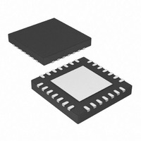
IC, 8BIT MCU, PIC16LF, 32MHZ, QFN-28
Manufacturer
Microchip Technology
Series
PIC® XLP™ 16Fr
Specifications of PIC16LF1827-I/MV
Controller Family/series
PIC16LF
Eeprom Memory Size
256Byte
Ram Memory Size
384Byte
Cpu Speed
32MHz
No. Of Timers
5
Interface
EUSART, I2C, SPI
Core Size
8 Bit
Program Memory Size
4kWords
Core Processor
PIC
Speed
32MHz
Connectivity
I²C, SPI, UART/USART
Peripherals
Brown-out Detect/Reset, POR, PWM, WDT
Number Of I /o
16
Program Memory Type
FLASH
Eeprom Size
256 x 8
Ram Size
384 x 8
Voltage - Supply (vcc/vdd)
1.8 V ~ 3.6 V
Data Converters
A/D 12x10b
Oscillator Type
Internal
Operating Temperature
-40°C ~ 85°C
Package / Case
28-UFQFN Exposed Pad
Processor Series
PIC16LF
Core
PIC
Data Ram Size
256 B
Maximum Clock Frequency
32 KHz
Number Of Programmable I/os
16
Number Of Timers
5
Operating Supply Voltage
1.8 V to 3.6 V
Maximum Operating Temperature
+ 125 C
3rd Party Development Tools
52715-96, 52716-328, 52717-734
Development Tools By Supplier
PG164130, DV164035, DV244005, DV164005
Minimum Operating Temperature
- 40 C
On-chip Adc
10 bit, 12 Channel
On-chip Dac
5 bit
Lead Free Status / RoHS Status
Lead free / RoHS Compliant
Lead Free Status / RoHS Status
Lead free / RoHS Compliant
Available stocks
Company
Part Number
Manufacturer
Quantity
Price


25.3.2
During the course of automatic baud detection, the
ABDOVF bit of the BAUDCON register will be set if the
baud rate counter overflows before the fifth rising edge
is detected on the RX pin. The ABDOVF bit indicates
that the counter has exceeded the maximum count that
can fit in the 16 bits of the SPBRGH:SPBRGL register
pair. After the ABDOVF has been set, the counter con-
tinues to count until the fifth rising edge is detected on
the RX pin. Upon detecting the fifth RX edge, the hard-
ware will set the RCIF interrupt flag and clear the
ABDEN bit of the BAUDCON register. The RCIF flag
can be subsequently cleared by reading the RCREG
register. The ABDOVF flag of the BAUDCON register
can be cleared by software directly.
To terminate the auto-baud process before the RCIF
flag is set, clear the ABDEN bit then clear the ABDOVF
bit of the BAUDCON register. The ABDOVF bit will
remain set if the ABDEN bit is not cleared first.
25.3.3
During Sleep mode, all clocks to the EUSART are
suspended. Because of this, the Baud Rate Generator
is inactive and a proper character reception cannot be
performed. The Auto-Wake-up feature allows the
controller to wake-up due to activity on the RX/DT line.
This feature is available only in Asynchronous mode.
The Auto-Wake-up feature is enabled by setting the
WUE bit of the BAUDCON register. Once set, the normal
receive sequence on RX/DT is disabled, and the
EUSART remains in an Idle state, monitoring for a
wake-up event independent of the CPU mode. A
wake-up event consists of a high-to-low transition on the
RX/DT line. (This coincides with the start of a Sync Break
or a wake-up signal character for the LIN protocol.)
The EUSART module generates an RCIF interrupt
coincident with the wake-up event. The interrupt is
generated synchronously to the Q clocks in normal CPU
operating modes (Figure 25-7), and asynchronously if
the device is in Sleep mode (Figure 25-8). The interrupt
condition is cleared by reading the RCREG register.
The WUE bit is automatically cleared by the low-to-high
transition on the RX line at the end of the Break. This
signals to the user that the Break event is over. At this
point, the EUSART module is in Idle mode waiting to
receive the next character.
2010 Microchip Technology Inc.
AUTO-BAUD OVERFLOW
AUTO-WAKE-UP ON BREAK
Preliminary
25.3.3.1
Break Character
To avoid character errors or character fragments during
a wake-up event, the wake-up character must be all
zeros.
When the wake-up is enabled the function works
independent of the low time on the data stream. If the
WUE bit is set and a valid non-zero character is
received, the low time from the Start bit to the first rising
edge will be interpreted as the wake-up event. The
remaining bits in the character will be received as a
fragmented character and subsequent characters can
result in framing or overrun errors.
Therefore, the initial character in the transmission must
be all ‘0’s. This must be 10 or more bit times, 13-bit
times recommended for LIN bus, or any number of bit
times for standard RS-232 devices.
Oscillator Start-up Time
Oscillator start-up time must be considered, especially
in applications using oscillators with longer start-up
intervals (i.e., LP, XT or HS/PLL mode). The Sync
Break (or wake-up signal) character must be of
sufficient length, and be followed by a sufficient
interval, to allow enough time for the selected oscillator
to start and provide proper initialization of the EUSART.
WUE Bit
The wake-up event causes a receive interrupt by
setting the RCIF bit. The WUE bit is cleared in
hardware by a rising edge on RX/DT. The interrupt
condition is then cleared in software by reading the
RCREG register and discarding its contents.
To ensure that no actual data is lost, check the RCIDL
bit to verify that a receive operation is not in process
before setting the WUE bit. If a receive operation is not
occurring, the WUE bit may then be set just prior to
entering the Sleep mode.
PIC16F/LF1826/27
Special Considerations
DS41391C-page 305
Related parts for PIC16LF1827-I/MV
Image
Part Number
Description
Manufacturer
Datasheet
Request
R

Part Number:
Description:
IC, 8BIT MCU, PIC16LF, 32MHZ, QFN-28
Manufacturer:
Microchip Technology
Datasheet:

Part Number:
Description:
IC, 8BIT MCU, PIC16LF, 32MHZ, DIP-18
Manufacturer:
Microchip Technology
Datasheet:

Part Number:
Description:
IC, 8BIT MCU, PIC16LF, 20MHZ, TQFP-44
Manufacturer:
Microchip Technology
Datasheet:
Part Number:
Description:
7 KB Flash, 384 Bytes RAM, 32 MHz Int. Osc, 16 I/0, Enhanced Mid Range Core, Nan
Manufacturer:
Microchip Technology

Part Number:
Description:
14KB Flash, 512B RAM, LCD, 11x10b ADC, EUSART, NanoWatt XLP 28 SOIC .300in T/R
Manufacturer:
Microchip Technology
Datasheet:
Part Number:
Description:
14KB Flash, 512B RAM, LCD, 11x10b ADC, EUSART, NanoWatt XLP 28 SSOP .209in T/R
Manufacturer:
Microchip Technology
Datasheet:
Part Number:
Description:
MCU PIC 14KB FLASH XLP 28-SSOP
Manufacturer:
Microchip Technology
Part Number:
Description:
MCU PIC 14KB FLASH XLP 28-SOIC
Manufacturer:
Microchip Technology
Part Number:
Description:
MCU PIC 512B FLASH XLP 28-UQFN
Manufacturer:
Microchip Technology
Part Number:
Description:
MCU PIC 14KB FLASH XLP 28-SPDIP
Manufacturer:
Microchip Technology

Part Number:
Description:
MCU 7KB FLASH 256B RAM 40-UQFN
Manufacturer:
Microchip Technology
Part Number:
Description:
MCU 7KB FLASH 256B RAM 44-TQFP
Manufacturer:
Microchip Technology

Part Number:
Description:
MCU 14KB FLASH 1KB RAM 28-UQFN
Manufacturer:
Microchip Technology
Part Number:
Description:
MCU PIC 14KB FLASH XLP 40-UQFN
Manufacturer:
Microchip Technology
Part Number:
Description:
MCU PIC 14KB FLASH XLP 44-TQFP
Manufacturer:
Microchip Technology