S29GL128P10FFI010 Spansion Inc., S29GL128P10FFI010 Datasheet - Page 41
S29GL128P10FFI010
Manufacturer Part Number
S29GL128P10FFI010
Description
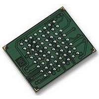
IC, FLASH, 128MBIT, 100NS, BGA-64
Manufacturer
Spansion Inc.
Datasheet
1.S29GL128P10FFI010.pdf
(80 pages)
Specifications of S29GL128P10FFI010
Memory Type
Flash
Memory Size
128Mbit
Memory Configuration
16M X 8 / 8M X 16
Ic Interface Type
CFI, Parallel
Access Time
100ns
Supply Voltage Range
2.7 To 3.6 V
Memory Case Style
BGA
Cell Type
NOR
Density
128Mb
Access Time (max)
100ns
Interface Type
Parallel
Boot Type
Not Required
Address Bus
24/23Bit
Operating Supply Voltage (typ)
3/3.3V
Operating Temp Range
-40C to 85C
Package Type
Fortified BGA
Sync/async
Asynchronous
Operating Temperature Classification
Industrial
Operating Supply Voltage (min)
2.7V
Operating Supply Voltage (max)
3.6V
Word Size
8/16Bit
Number Of Words
16M/8M
Supply Current
110mA
Mounting
Surface Mount
Pin Count
64
Rohs Compliant
Yes
Lead Free Status / RoHS Status
Lead free / RoHS Compliant
Available stocks
Company
Part Number
Manufacturer
Quantity
Price
Company:

Part Number:
S29GL128P10FFI010
Manufacturer:
XILINX
Quantity:
364
Part Number:
S29GL128P10FFI010
Manufacturer:
SPANSION
Quantity:
20 000
Company:
Part Number:
S29GL128P10FFI010A
Manufacturer:
SPANSION
Quantity:
10 393


November 17, 2010 S29GL-P_00_A13
7.9.3
Software Reset
Software reset is part of the command set (see
read mode and must be used for the following conditions:
Software Functions and Sample Code
Note
Base = Base Address.
The following is a C source code example of using the reset function. Refer to the Spansion Low Level Driver
User’s Guide (available on www.spansion.com) for general information on Spansion Flash memory software
development guidelines.
The following are additional points to consider when using the reset command:
This command resets the sectors to the read and address bits are ignored.
Reset commands are ignored during program and erase operations.
The reset command may be written between the cycles in a program command sequence before
If the program command sequence is written to a sector that is in the Erase Suspend mode, writing the
The reset command may be written during an Autoselect command sequence.
If a sector has entered the Autoselect mode while in the Erase Suspend mode, writing the reset command
If DQ1 goes high during a Write Buffer Programming operation, the system must write the “Write to Buffer
To exit the unlock bypass mode, the system must issue a two-cycle unlock bypass reset command
/* Example: Reset (software reset of Flash state machine) */
programming begins (prior to the third cycle). This resets the sector to which the system was writing to the
read mode.
reset command returns that sector to the erase-suspend-read mode.
returns that sector to the erase-suspend-read mode.
Abort Reset” command sequence to RESET the device to reading array data. The standard RESET
command does not work during this condition.
sequence [see
1. to exit Autoselect mode
2. when DQ5 goes high during write status operation that indicates program or erase cycle was not
3. exit sector lock/unlock operation.
4. to return to erase-suspend-read mode if the device was previously in Erase Suspend mode.
5. after any aborted operations
*( (UINT16 *)base_addr ) = 0x00F0;
successfully completed
Reset Command
Cycle
Command Definitions on page 68
D a t a
S29GL-P MirrorBit
S h e e t
Operation
(LLD Function = lld_ResetCmd)
Write
Table 7.18 Reset
®
Table 12.1 on page
Flash Family
for details].
Byte Address
Base + xxxh
69) that also returns the device to array
Word Address
Base + xxxh
00F0h
Data
41
Related parts for S29GL128P10FFI010
Image
Part Number
Description
Manufacturer
Datasheet
Request
R

Part Number:
Description:
Flash 3V 32Mb Float Gate two address 90s
Manufacturer:
Spansion Inc.
Datasheet:
Part Number:
Description:
Flash 3V 64Mb Float Gate two address 90s
Manufacturer:
Spansion Inc.
Datasheet:

Part Number:
Description:
Flash 3V 64Mb Float Gate standard config 90s
Manufacturer:
Spansion Inc.
Datasheet:

Part Number:
Description:
Flash 3V 1 Gb Mirrorbit highest address120ns
Manufacturer:
Spansion Inc.
Datasheet:

Part Number:
Description:
Flash 3V 256Mb Mirrorbit highest address110ns
Manufacturer:
Spansion Inc.
Datasheet:
Part Number:
Description:
Flash 3V 64Mb Float Gate highest address 90s
Manufacturer:
Spansion Inc.
Datasheet:
Part Number:
Description:
Flash 3V 512Mb Mirrorbit lowest address100ns
Manufacturer:
Spansion Inc.
Datasheet:
Part Number:
Description:
Flash 3V 32Mb Float Gate highest address 90s
Manufacturer:
Spansion Inc.
Datasheet:
Part Number:
Description:
Flash 3V 64Mb Float Gate highest address 90s
Manufacturer:
Spansion Inc.
Datasheet:
Part Number:
Description:
Flash 3V 1 Gb Mirrorbit highest address110ns
Manufacturer:
Spansion Inc.
Datasheet:
Part Number:
Description:
Flash 3V 256Mb Mirrorbit lowest address110ns
Manufacturer:
Spansion Inc.
Datasheet:
Part Number:
Description:
Flash 3V 512Mb Mirrorbit highest address110ns
Manufacturer:
Spansion Inc.
Datasheet:
Part Number:
Description:
Flash 3V 128Mb Mirrorbit lowest address110ns
Manufacturer:
Spansion Inc.
Datasheet:
Part Number:
Description:
Flash 3V 64Mb Float Gate standard config 70s
Manufacturer:
Spansion Inc.

Part Number:
Description:
IC, FLASH, 1MBIT, 70NS, LCC-32
Manufacturer:
Spansion Inc.
Datasheet: