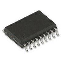
74LV244D NXP Semiconductors, 74LV244D Datasheet - Page 6

74LV244D
Manufacturer Part Number
74LV244D
Description
74LV, SMD, 74LV244, SOIC20, 3.3V
Manufacturer
NXP Semiconductors
Datasheet
1.74LV244D.pdf
(12 pages)
Specifications of 74LV244D
Supply Voltage Range
1V To 5.5V
Logic Case Style
SOIC
No. Of Pins
20
Operating Temperature Range
-40°C To +125°C
Svhc
No SVHC (18-Jun-2010)
Base Number
74
Ic Generic
RoHS Compliant
Package / Case
SOIC
Logic Device Type
Buffer / Line Driver, Non Inverting
Rohs Compliant
Yes
Available stocks
Company
Part Number
Manufacturer
Quantity
Price
Company:
Part Number:
74LV244D
Manufacturer:
PHIL
Quantity:
865
Part Number:
74LV244D
Manufacturer:
NXP/恩智浦
Quantity:
20 000
Part Number:
74LV244D+118
Manufacturer:
NXP/恩智浦
Quantity:
20 000
Part Number:
74LV244D,118
Manufacturer:
NXP/恩智浦
Quantity:
20 000
Company:
Part Number:
74LV244D118
Manufacturer:
NXP
Quantity:
2 253
Company:
Part Number:
74LV244DB,118
Manufacturer:
NXP Semiconductors
Quantity:
10
1. Unless otherwise stated, all typical values are measured at T
2. Typical values are measured at V
Philips Semiconductors
AC CHARACTERISTICS
GND = 0V; t
NOTES:
AC WAVEFORMS
V
V
V
output load.
V
V
V
V
1998 May 20
SYMBOL
M
M
OL
X
X
Y
Y
t
t
t
PHL/
PZH/
PHZ/
Octal buffer/line driver (3-State)
= V
= V
= V
= V
= 1.5 V at V
= 0.5
and V
t
t
t
OL
OL
OH
OH
PLH
PZL
PLZ
OUTPUT
1A
1Y
INPUTS
Figure 1. Input (1A
+ 0.3 V at V
+ 0.1
OH
– 0.3 V at V
– 0.1
n
n
, 2A
GND
, 2Y
V
V
V
r
OH
CC
OL
= t
are the typical output voltage drop that occur with the
V
n
n
I
Propagation delay
Pro agation delay
1A
2A to 2Y
2A
3-State output enable time
3-State out ut enable time
1OE to 1Y
2OE to 2Y
2OE to 2Y
3-State output disable time
3-State out ut disable time
1OE to 1Y
2OE to 2Y
2OE to 2Y
CC
f
at V
n
n
V
V
t
PHL
2.5ns; C
to 1Y
to 2Y
CC
CC
CC
2.7 V and
CC
PARAMETER
CC
at V
at V
propagation delays.
n
n
n
n
n
n
2.7 V and
;
CC
;
;
2.7 V and
V
CC
2.7V and
L
M
= 50pF; R
n
V
2.7 V and
, 2A
M
2.7 V and
3.6 V
n
) to output (1Y
CC
4.5 V
3.6 V
3.6 V
L
= 3.3 V.
=1K
4.5 V
4.5 V
WAVEFORM
Figures 1, 2
Figures 2, 3
Figures 2, 3
n
, 2Y
SV00617
t
PLH
n
)
amb
CONDITION
CONDITION
= 25 C.
3.0 to 3.6
4.5 to 5.5
3.0 to 3.6
4.5 to 5.5
3.0 to 3.6
4.5 to 5.5
V
6
CC
1.2
2.0
2.7
1.2
2.0
2.7
1.2
2.0
2.7
(V)
HIGH-to-OFF
OFF-to-HIGH
LOW-to-OFF
OFF-to-LOW
Q
Q
n
n
OE INPUT
OUTPUT
OUTPUT
Figure 2. 3-State enable and disable times.
GND
GND
V
V
MIN
V
CC
OH
OL
V
I
–40 to +85 C
enabled
outputs
TYP
12
13
50
17
13
9
65
22
16
60
22
17
V
t
2
M
PLZ
t
2
2
PHZ
1
LIMITS
V
MAX
X
24
17
14
12
39
29
23
19
34
24
21
16
V
Y
disabled
outputs
–40 to +125 C
MIN
t
PZL
Product specification
t
PZH
74LV244
MAX
31
23
18
15
49
36
29
24
43
32
26
19
V
M
V
M
SV00623
outputs
enabled
UNIT
ns
ns
ns


