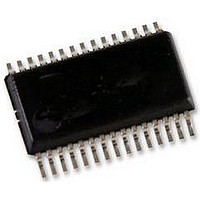
TB6562AFG Toshiba, TB6562AFG Datasheet - Page 5

TB6562AFG
Manufacturer Part Number
TB6562AFG
Description
IC, STEPPER MOTOR DRIVER, 40V 1.5A
Manufacturer
Toshiba
Datasheet
1.TB6562AFGOEL.pdf
(19 pages)
Specifications of TB6562AFG
No. Of Outputs
2
Output Current
1.5A
Output Voltage
40V
Supply Voltage Range
0V To 5V, 10V To 34V
Driver Case Style
SSOP
No. Of Pins
30
Operating Temperature Range
-20°C To +85°C
Package /
RoHS Compliant
Motor Type
Stepper
Rohs Compliant
Yes
Function
Driver
Vopmax (vm*)
34V (40V)
Io (lpeak)
(1.5A)
Excitation
1/4 step
I/f
phase input (2-bit/phase)
Mixed Decay Mode
no
Package
SSOP30
Rohs Compatible†
yes
Available stocks
Company
Part Number
Manufacturer
Quantity
Price
Company:
Part Number:
TB6562AFG
Manufacturer:
TOS
Quantity:
376
Part Number:
TB6562AFG
Manufacturer:
TOSHIBA/东芝
Quantity:
20 000
Absolute Maximum Ratings
exceeded during operation, even for an instant.
altered, in which case the reliability and lifetime of the device can no longer be guaranteed.
equipment. Applications using the device should be designed so that no maximum rating will ever be exceeded under
any operating condition.
this document.
Operating Range
The absolute maximum ratings of a semiconductor device are a set of specified parameter values that must not be
If any of these ratings are exceeded during operation, the electrical characteristics of the device may be irreparably
Moreover, any exceeding of the ratings during operation may cause breakdown, damage and/or degradation in other
Before using, creating and/or producing designs, refer to and comply with the precautions and conditions set forth in
Note 1: Output current may be controlled by excitation mode, ambient temperature, or heatsink.
Note 2: When mounted on a board (50 mm × 50 mm × 1.6 mm, Cu area: 50%)
Power supply voltage
Output voltage
Output current
Input voltage
Power dissipation
Operating temperature
Storage temperature
Junction temperature
Power supply voltage
Input voltage
Vref voltage
PWM frequency
Triangular-wave oscillation frequency
When designing a circuit, ensure that the maximum junction temperature, TjMAX = 150°C, is not exceeded
when the IC is used.
Avoid using the IC in abnormal conditions that would cause the Tj to exceed 150°C, even though the heat
protection circuit of the IC will continue to operate in such conditions.
Characteristic
Characteristic
(Ta = –20 to 85°C)
(Ta = 25°C)
I
Symbol
Symbol
O (Peak)
Tjmax
fpwm
V CC
V
T
T
Vref
f
Vin
Vin
P
Vo
osc
CC
opr
stg
D
−0.2 to 5.5
−55 to 150
0.5 to 7.0
45 to 400
−20 to 85
10 to 34
15 to 80
Rating
Rating
0 to 5
150
1.5
2.5
40
40
5
(Note 1)
(Note 2)
Unit
Unit
kHz
kHz
°C
°C
°C
W
V
V
A
V
V
V
V
TB6562ANG/AFG
2007-3-22


